Replacing sharing resistors, Silicon controlled rectifier powercages – Rockwell Automation 7000 PowerFlex Medium Voltage AC Drive (B Frame) - ForGe Control User Manual
Page 78
78
Rockwell Automation Publication 7000-UM202B-EN-P - June 2014
Chapter 3
Component Definition and Maintenance
5.
Remove the capacitor from the PowerCage.
6.
Place the new capacitor back into the PowerCage.
Ensure the bottom lead of the capacitor is on the stud.
7.
Slide the retaining rod into place and push the clips back into place.
8.
Connect the top lead to the capacitor.
9.
Install the PowerCage as outlined in
Replacing Sharing Resistors
Normally the sharing resistor is part of the snubber resistor assembly. Replacing
the sharing resistor requires also replacing the snubber resistor.
The sharing and snubber resistors are normally located on the backside of the
PowerCage. See
for removing and replacing snubber resistors.
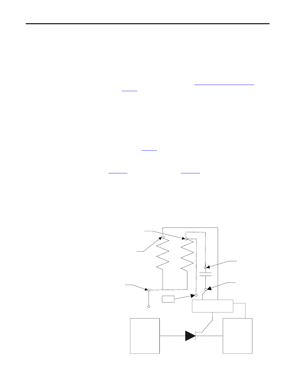
Silicon Controlled Rectifier
PowerCages
shows the snubber circuit.
shows the physical locations of the
same circuit.
Disconnect the 2-pole plug to the Gate Driver board marked TB1 on the circuit
board. Measure the resistance from the point of the plug that connects to the
point labeled V.SENSE on the Gate Driver board to the anode side heat sink. A
value of 80 kΩ indicates a good sharing resistor.
Figure 71 - Snubber Circuit for SCR Rectifier Module
T P
R s n-2
C s -1
Rs h
A node
C s -2
S P G D B
Cathode
R s n-1