Rockwell Automation 7000 PowerFlex Medium Voltage AC Drive (B Frame) - ForGe Control User Manual
Page 36
36
Rockwell Automation Publication 7000-UM202B-EN-P - June 2014
Chapter 3
Component Definition and Maintenance
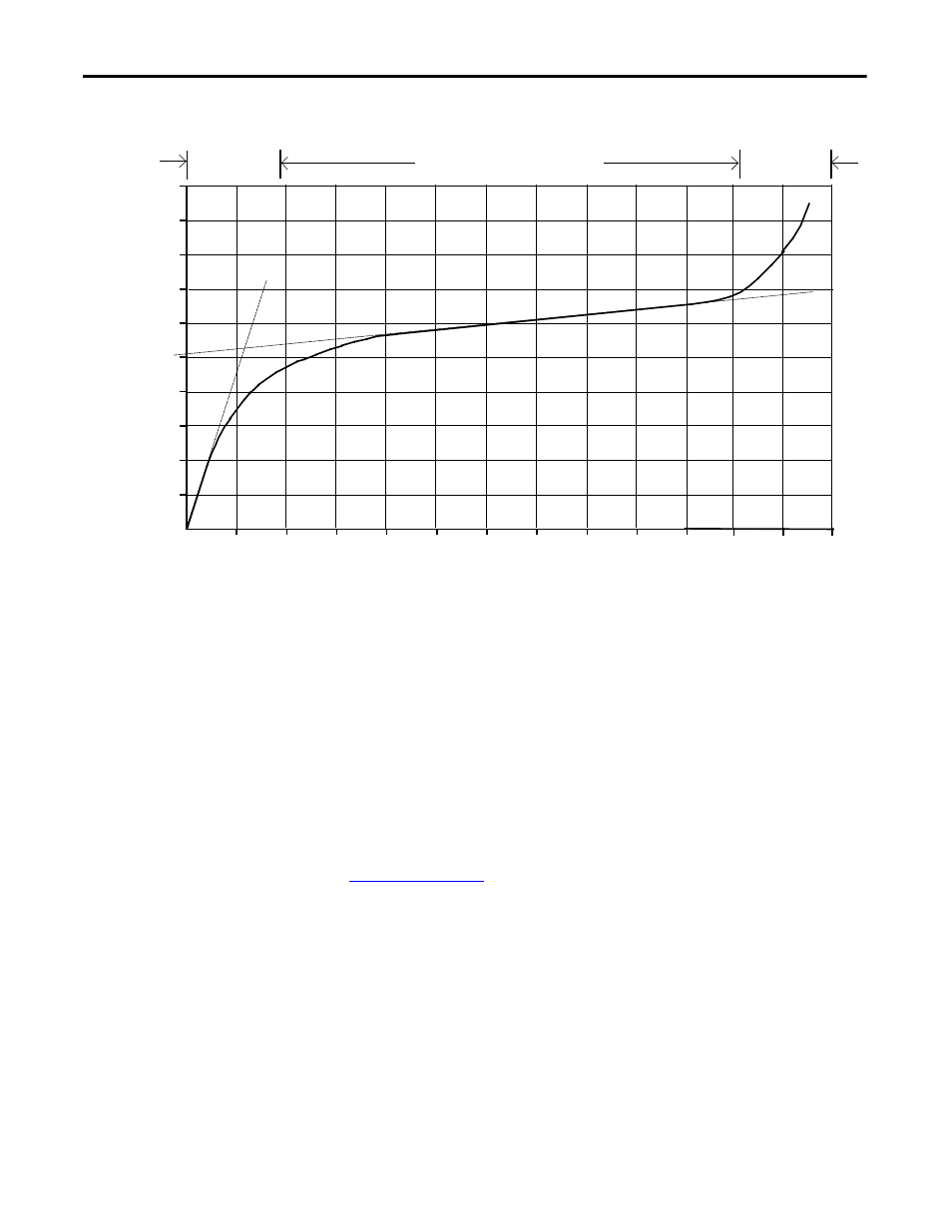
Figure 26 - Typical MOV V-I Characteristic Curve
When the MOV clips the voltage transient, the MOV absorbs the transient
energy. The varistor has a limited energy absorbing capability and there is
insufficient time to conduct heat out of the device. The MOV size depends on
the steady-state voltage rating, the energy in the transient, and the repetition rate
of the transients. A critical element in selecting a MOV for protection is the
impedance in the line supplying the transient. The isolation transformer or the
AC line reactor on the input of the drive provides this impedance, which is why
an impedance level is necessary for these input devices.
MOV Fuse
A medium voltage fuse is in series with each of the Phase MOVs. As seen in
, these fuses may reside on either the assembly or remote
from the assembly (on the Line Terminal module). Check the part number on
your module and the information in this documentation to determine which
assembly your drive requires.
The fuses provide overload protection for the conductors feeding the suppression
network (and overturned protection if a short circuit occurs on the downstream
side of the fuse.) These conductors will normally have a much smaller current
carrying capacity than the drive input conductors; they are not protected by the
drive input fuses. The fuses also isolate a failed MOV. Varistors initially fail in a
short-circuited condition. The high follow-through current will open the fuse
and remove the MOV from the circuit.
10
-7
10
-6
10
-5
10
-4
10
-3
10
-2
10
-1
10
0
10 10
2
10
3
10
4
10
5
10
-8
CURRENT (AMPERES) -log scale
VOLTAGE
(VOLTS)
lo
g sc
al
e
High Resistance
Region
Voltage Clamping Region
Short Circuit
Region