Impeller maintenance, Impeller removal from motor shaft – Rockwell Automation 7000 PowerFlex Medium Voltage AC Drive (B Frame) - ForGe Control User Manual
Page 120
120
Rockwell Automation Publication 7000-UM202B-EN-P - June 2014
Chapter 3
Component Definition and Maintenance
Impeller Maintenance
The fan impeller connects to the motor shaft with a split tapered bushing. This
bushing is positioned on the motor shaft and through the center of the impeller.
Two cap screws, when tightened to 10.2 N•m (7.5 lb•ft), lock the bushing onto
the motor shaft and the impeller to the bushing.
Impeller Removal from Motor Shaft
Safety Notes
The impeller is not designed to support the weight of the motor.
If vertical, the impeller and bushing may fall when loosening cap screws. Physical
injury or component damage may result.
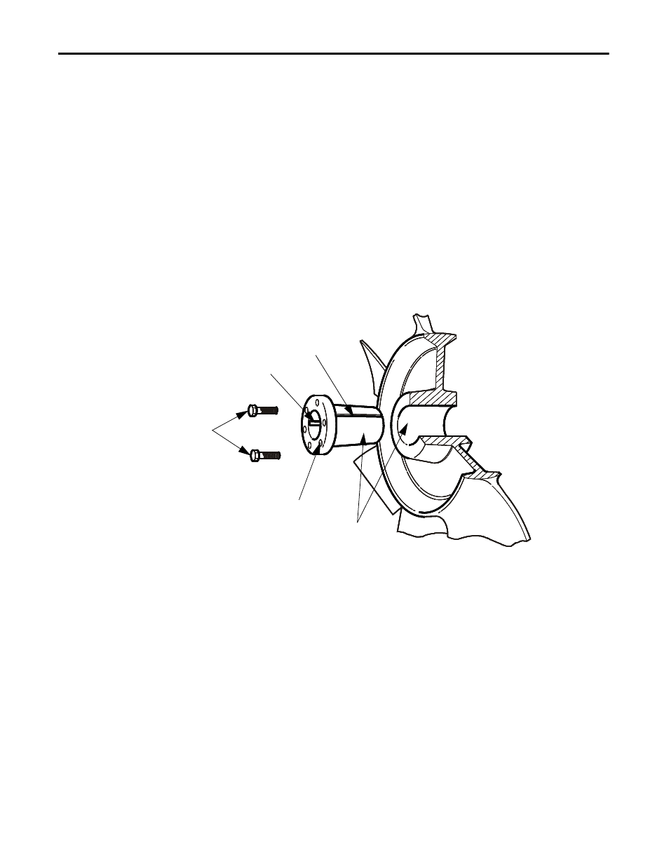
Figure 107 - Impeller Removal
1.
Record the distance from the end of the motor shaft to the bushing. The
new impeller must be installed in the same location. Failure to do so will
result in gaps between the impeller and the intake ring resulting in loss of
air flow, or rubbing of the impeller against the inlet ring or motor assembly
during operation.
2.
Remove both cap screws from the bushing. The impeller or bushing may
fall as screws are loosened.
3.
Thread the cap screws by hand into the two threaded holes in the bushing
flange.
Capscrews
Threaded Hole for
Separating Tapers
Key
Split in Taper Bushing
Taper Surfaces