System wiring – Rockwell Automation 25-COMM-E2P PowerFlex 25-COMM-E2P Dual-Port EtherNet/IP Adapter User Manual
Page 89
Rockwell Automation Publication 520COM-UM003A-EN-E - June 2013
89
Using Multi-Drive Mode
Chapter 7
•
Communications throughput to the daisy-chained drives will be slower
than if each drive was a separate node on EtherNet/IP (Single-drive
mode). This is because the Dual-port EtherNet/IP adapter must take the
EtherNet/IP data for the other drives and sequentially send the respective
data to each drive over RS-485. The approximate additional throughput
time for Logic Command/Reference to be transmitted and received by
each drive is:
•
Since the RS-485 ports are used for daisy-chaining the drives, there is no
connection for a peripheral device such as a HIM or USB converter
module (1203-USB). DSI Splitter cables cannot be used to add a second
connection for a peripheral device.
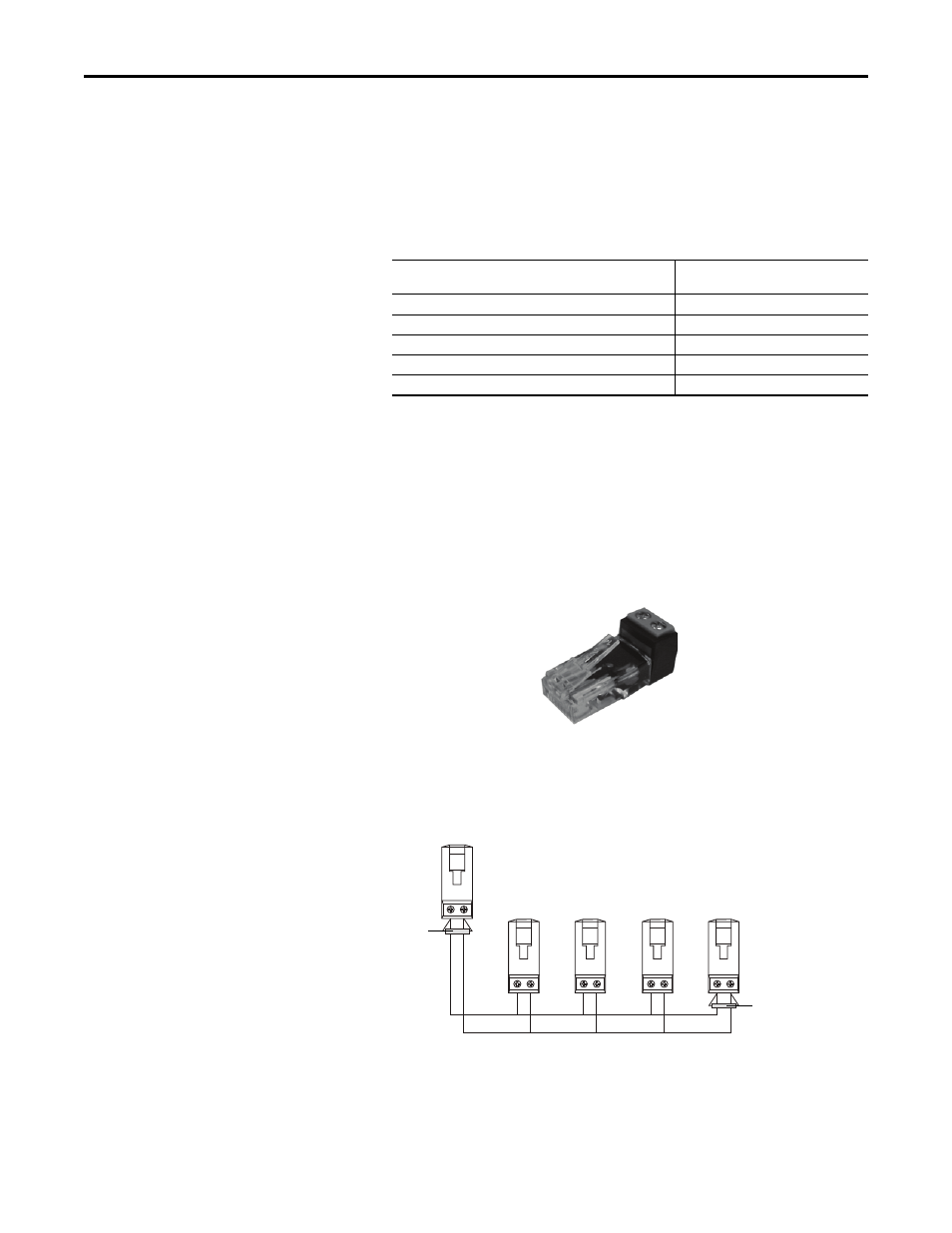
System Wiring
To daisy-chain the drives to the PowerFlex 525, the AK-U0-RJ45-TB2P terminal
block connector can be used for easy installation.
The wiring diagram for using AK-U0-RJ45-TB2P terminal block connectors is
shown below.
The AK-U0-RJ45-TB2P comes with (5) terminal block connectors and (2)
terminating resistors.
Drive
Additional Throughput Time
versus Single-Drive Mode
PowerFlex 525
0 ms
PowerFlex 525 plus 1 drive
+24 ms
PowerFlex 525 plus 2 drives
+48 ms
PowerFlex 525 plus 3 drives
+72 ms
PowerFlex 525 plus 4 drives
+96 ms
To PowerFlex 525 with
25-COMM-E2P
To Drive #2
To Drive #3
To Drive #4
To Drive #5
120
Ω
, 1/4 W
resistor
120
Ω
, 1/4 W
resistor