Rockwell Automation 25-COMM-E2P PowerFlex 25-COMM-E2P Dual-Port EtherNet/IP Adapter User Manual
Page 128
128
Rockwell Automation Publication 520COM-UM003A-EN-E - June 2013
Appendix B
Adapter Parameters
24
[Idle Flt Action]
Sets the Idle (Program mode) action of the drive, if the adapter
detects that the controller has transitioned to program mode.
Important: This setting is effective when the drive’s control
source is transmitted through the adapter. When the controller
is returned to Run mode, the drive will again be controlled from
the network adapter.
Default:
0 = Fault
Values:
0 = Fault
1 = Stop
2 = Zero Data
3 = Hold Last
4 = Send Flt Cfg
Type:
Read/Write
Reset Required:
No
25
[Flt Cfg Logic]
Sets the Logic Command data that is sent to the drive if any of
the following is true:
• Device parameter 23 [Comm Flt Action] is set to 4 “Send Flt
Cfg” and I/O communications is disrupted.
• Device parameter 24 [Idle Flt Action] is set to 4 “Send Flt Cfg”
and the controller is in Program Mode.
Default:
0000 0000 0000 0000
Minimum:
0000 0000 0000 0000
Maximum:
1111 1111 1111 1111
Type:
Read/Write
Reset Required:
No
26
[Flt Cfg Ref]
Sets the Reference data that is sent to the drive if any of the
following is true:
• Device parameter 23 [Comm Flt Action] is set to 4 “Send Flt
Cfg” and I/O communications is disrupted.
• Device parameter 24 [Idle Flt Action] is set to 4 “Send Flt Cfg”
and the controller is in Program Mode.
Default:
0
Minimum:
0
Maximum:
65535
Type:
Read/Write
Reset Required:
No
27
28
29
30
[Flt Cfg DL 1]
[Flt Cfg DL 2]
[Flt Cfg DL 3]
[Flt Cfg DL 4]
Sets the data that is sent to the Datalink in the drive if any of the
following is true:
• Device parameter 23 [Comm Flt Action] is set to 4 “Send Flt
Cfg” and I/O communications is disrupted.
• Device parameter 24 [Idle Flt Action] is set to 4 “Send Flt Cfg”
and the controller is in Program Mode.
Default:
0
Default:
0
Default:
0
Default:
0
Minimum:
0
Maximum:
65535
Type:
Read/Write
Reset Required:
No
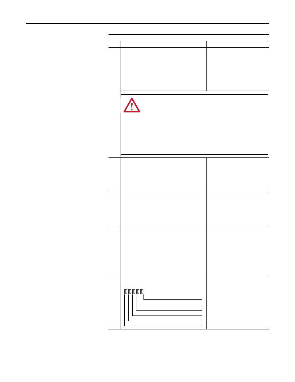
31
[DSI I/O Act]
Displays the Drives that are active in the Multi-drive mode.
Bit Definitions:
0 = Drive Active
1 = Drive Inactive
Digits:
0 = Drive 0 Actv
1 = Drive 1 Actv
2 = Drive 2 Actv
3 = Drive 3 Actv
4 = Drive 4 Actv
Type:
Read Only
Parameter
No.
Name and Description
Details
ATTENTION: Risk of injury or equipment damage exists. Device
parameter 24 [Idle Flt Action] lets you determine the action of the
adapter and connected drive if the controller is idle. By default, this
parameter faults the drive. you can set this parameter so that the drive
continues to run. Precautions should be taken to ensure that the
setting of this parameter does not create a risk of injury or equipment
damage. When commissioning the drive, verify that your system
responds correctly to various situations (for example, a disconnected
drive).
1 = Drive Inactive, 0 = Drive Active
Drive 0 Actv
Digit 1
Drive 1 Actv
Digit 2
Drive 2 Actv
Digit 3
Drive 3 Actv
Digit 4
Drive 4 Actv
Digit 5