Connecting the adapter to the drive, Setting the node address – Rockwell Automation 25-COMM-E2P PowerFlex 25-COMM-E2P Dual-Port EtherNet/IP Adapter User Manual
Page 18
18
Rockwell Automation Publication 520COM-UM003A-EN-E - June 2013
Chapter 2
Installing the Adapter
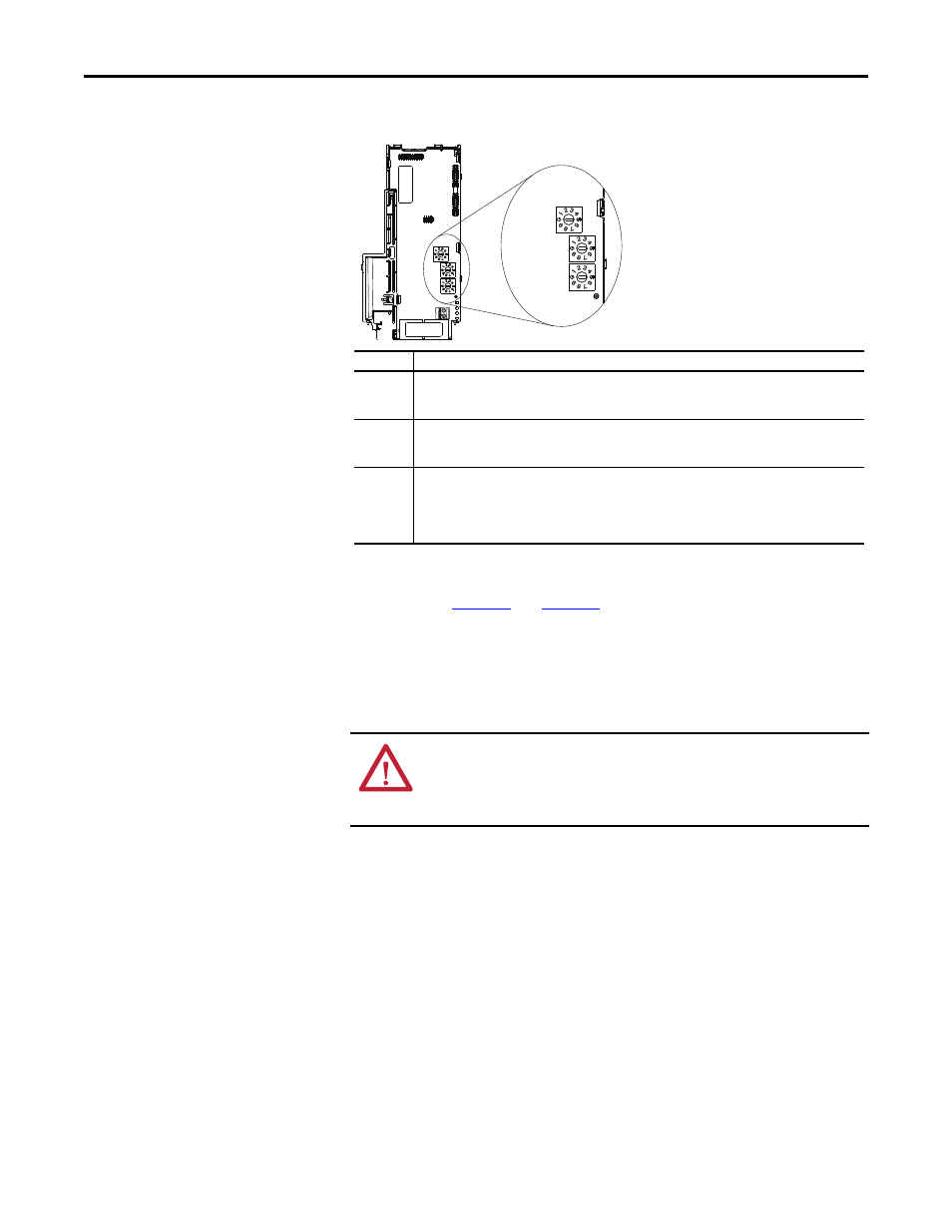
Setting the Node Address Switches
The Node Address switch settings can be verified by viewing Diagnostic Item
number 58 (see
and
) with a PowerFlex 22-HIM-A3 or 22-
HIM-C2S HIM, or Connected Components Workbench (version 3 or greater)
software. Also, you can use
Device parameter 05 [Net Addr Src], a read-only
parameter, to verify the selected setting for
Device parameter 04 [Net Addr Sel].
Connecting the Adapter to
the Drive
1.
Remove power from the drive.
2.
Use static control precautions.
3.
Separate the drive’s control module from the power module.
Hundreds
position
Tens
position
Ones
position
Setting
Description
001...254
The adapter will use the Node Address switch settings for the network node address (192.168.1.xxx,
where xxx = rotary switch settings). The value stored in Device parameter 04 [Net Addr Sel] is
automatically ignored.
888
Resets the adapter network node address to factory defaults. Thereafter, the drive must be powered
down, the Node Address switches must be set to a correct value (001…254), and then the drive must be
powered up again to accept the new address.
Any other
setting
Disables the Node Address switches, and requires using Device parameter 04 [Net Addr Sel] to select
the source for the adapter’s network node address:
• 1 = Parameters of the adapter
• 2 = BOOTP server
• 3 = DHCP server (Default)
ATTENTION: Risk of injury or death exists. The PowerFlex drive may contain
high voltages that can cause injury or death. Remove all power from the
PowerFlex drive, and then verify power has been removed before installing or
removing an adapter.