Applying power, Startup status indication – Rockwell Automation 25-COMM-E2P PowerFlex 25-COMM-E2P Dual-Port EtherNet/IP Adapter User Manual
Page 22
22
Rockwell Automation Publication 520COM-UM003A-EN-E - June 2013
Chapter 2
Installing the Adapter
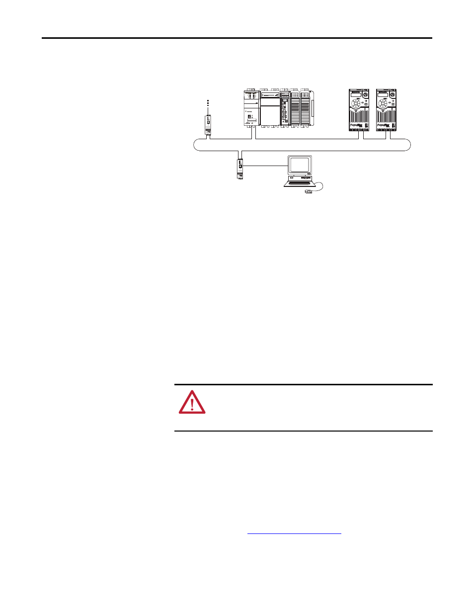
Connecting the Ethernet Cable in a DLR Topology Network
4.
Depending on the network topology, do one of the following:
•
Star Network Topology—Route the other end of the Ethernet cable
from the network through the bottom of the drive, and insert its cable
plug into the option module’s ENET1 or ENET2 network port.
•
Linear or DLR Network Topology—Route the other end of the
Ethernet cable from the network through the bottom of the first drive,
and insert its cable plug into the option module ENET1 network port.
To connect to the second drive, attach another Ethernet cable between
the first drive’s option module ENET2 network port and the second
drive’s option module ENET1 network port.
To connect additional drives, repeat these daisy-chain connections in
the same way.
Applying Power
Apply power to the drive. The adapter receives its power from the drive.
Startup Status Indication
After power has been applied, the status indicators can be viewed on the front of
the drive. When you apply power to the adapter for the first time, the status
indicators should be green after an initialization. If the status indicators go red,
there is a problem. See
.
1 (Front)
1 (Front)
1 (Front)
2 (Rear)
00:00:BC:2E:69:F6
Esc
Sel
Esc
Sel
1783-ETAP
1769-L36ERM CompactLogix controller
with embedded EtherNet/IP bridge
PowerFlex 520-series drives with
25-COMM-E2P adapter
(1)
(Frame A shown)
Computer with
Ethernet Connection
To other
EtherNet/IP
networks
(1) The adapter’s ENET1 and ENET2 network ports are used.
1783-ETAP
ATTENTION: Risk of equipment damage, injury, or death exists. Unpredictable
operation may occur if you fail to verify that parameter settings are compatible
with your application. Verify that settings are compatible with your application
before applying power to the drive.