Net b status indicator, Viewing adapter diagnostic items – Rockwell Automation 25-COMM-E2P PowerFlex 25-COMM-E2P Dual-Port EtherNet/IP Adapter User Manual
Page 117
Rockwell Automation Publication 520COM-UM003A-EN-E - June 2013
117
Troubleshooting
Chapter 8
NET B Status Indicator
This green LED indicates the status of the adapter transmitting on the network
as shown in the table below.
Viewing Adapter Diagnostic
Items
If you encounter unexpected communications problems, the adapter’s diagnostic
items may help you or Rockwell Automation personnel troubleshoot the
problem. The diagnostic parameters for the Dual-port EtherNet/IP adapter can
be viewed using the PowerFlex 22-HIM-A3/-C2S HIM or Connected
Components Workbench software.
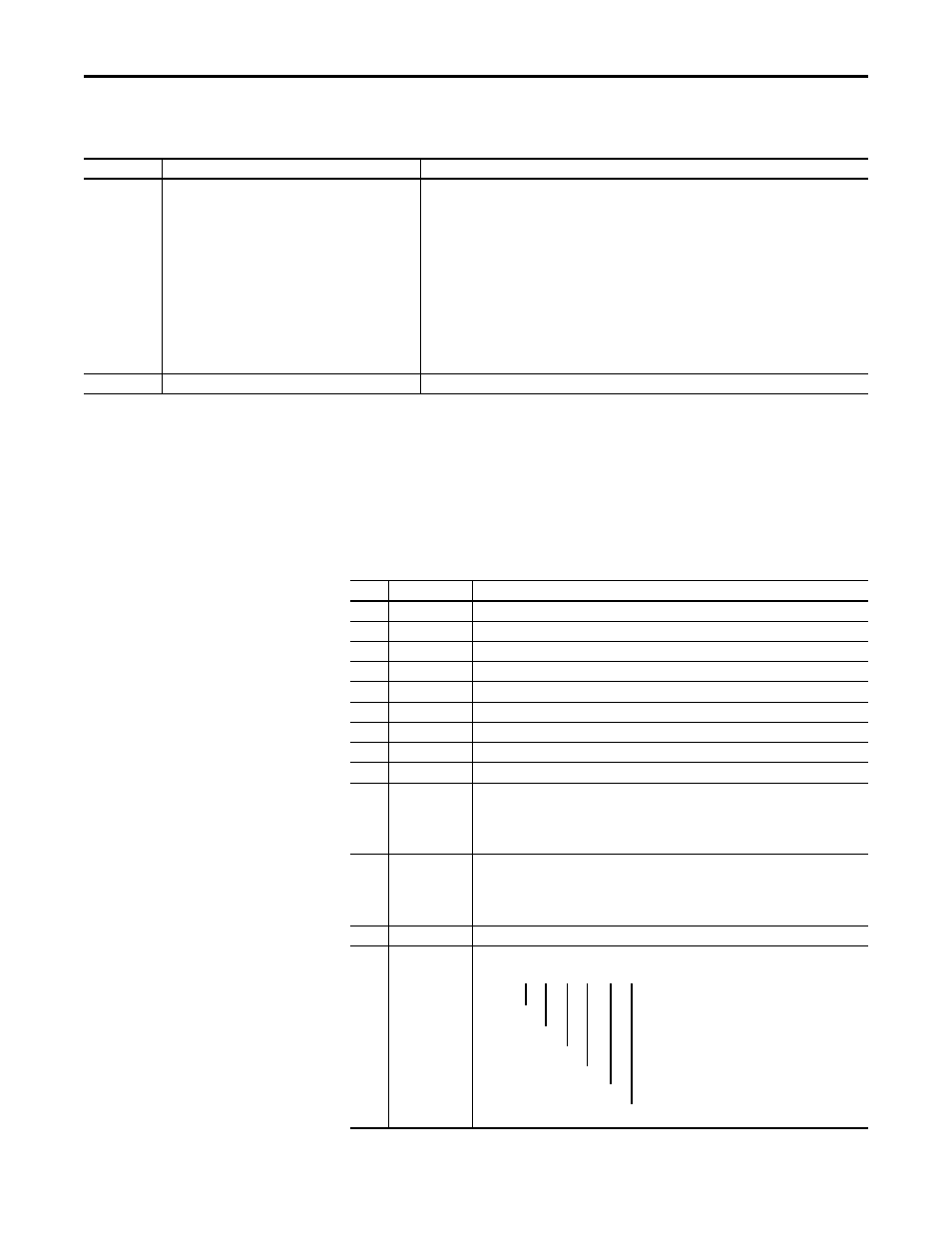
Status
Cause
Corrective Actions
Off
This adapter is not transmitting on the network.
If Net A indicator is off:
• Securely connect the adapter to the drive, then connect the adapter to the network using an Ethernet
cable.
• Correctly connect the Ethernet cable to the Ethernet connector.
• Set a unique IP address with the adapter rotary switches, adapter parameters, or a BOOTP or DHCP
server.
If Net A indicator is steady red:
• Configure the adapter to use a unique IP address and cycle power to the drive.
If Net A indicator is flashing red/green or red:
• Check the IP address in the adapter and scanner, and verify that the controller can communicate with
the adapter.
• Ping the adapter.
• Normal condition if the adapter is idle.
Flashing green
The adapter is transmitting on the network.
No action required.
Dual-port EtherNet/IP Adapter Diagnostic Items in Single-Drive Mode
No.
Name
Description
01
Reserved
–
02
Logic Cmd
The present value of the Logic Command being transmitted to the drive by this adapter.
03
Reference
The present value of the Reference being transmitted to the drive by this adapter.
04
Reserved
–
05
Logic Sts
The present value of the Logic Status being received from the drive by this adapter.
06
Feedback
The present value of the Feedback being received from the drive by this adapter.
07...22 Reserved
–
23
Input Size
Displays the size of the input image in bytes transferred from the network to the drive.
24
Output Size
Displays the size of the output image in bytes transferred from the drive to the network.
25
26
27
28
DL Fr Net 01 Val
DL Fr Net 02 Val
DL Fr Net 03 Val
DL Fr Net 04 Val
The current datalink value being transmitted from this adapter to the drive.
29
30
31
32
DL To Net 01 Val
DL To Net 02 Val
DL To Net 03 Val
DL To Net 04 Val
The current datalink value being received from the drive by this adapter.
33
Opt Comm Errs
A count of the number of adapter to drive communication errors
34
35
36
37
38
39
HW Addr 1
HW Addr 2
HW Addr 3
HW Addr 4
HW Addr 5
HW Addr 6
Decimal value of each octet in the adapter’s Ethernet hardware address.
255.255.255.255.255.255
[HW Addr 1]
[HW Addr 2]
[HW Addr 3]
[HW Addr 4]
[HW Addr 5]
[HW Addr 6]