8commissioning of the canopen logic bus – Lenze CANopen Controller-based Automation User Manual
Page 40
Lenze · Controller-based Automation · CANopen® Communication Manual · DMS 6.3 EN · 04/2014 · TD17
40
8
Commissioning of the CANopen Logic bus
8.5
Creating a PLC program with a target system (Logic)
_ _ _ _ _ _ _ _ _ _ _ _ _ _ _ _ _ _ _ _ _ _ _ _ _ _ _ _ _ _ _ _ _ _ _ _ _ _ _ _ _ _ _ _ _ _ _ _ _ _ _ _ _ _ _ _ _ _ _ _ _ _ _ _
8.5
Creating a PLC program with a target system (Logic)
The »PLC Designer« serves to model the network topology in the control configuration.
Tip!
The »PLC Designer« can be used to configure CANopen nodes and nodes on other fieldbus
systems.
Mixed operation of CANopen and EtherCAT
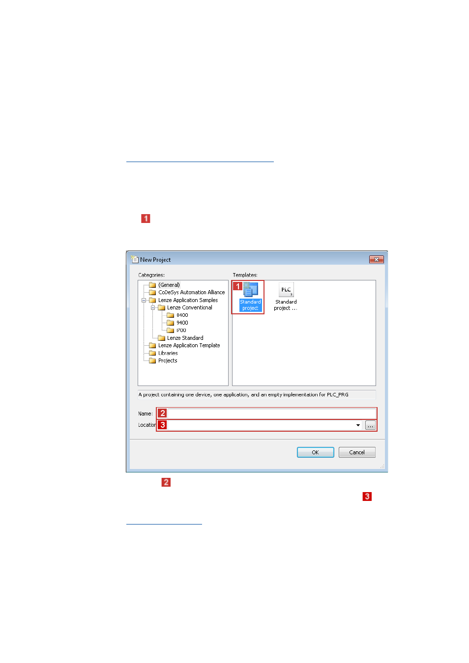
How to create a PLC program in the »PLC Designer«:
1. Use the menu command File New project to create a new »PLC Designer« project.
2. Select
"Standard project" in the New Project dialog window.
A "Standard object" simplifies the structure of a project in the »PLC Designer«; for instance,
a device tree structure with a target system, PLC logic, etc. is provided.
• Go to the
Name input field and enter a name for your »PLC Designer« project.
• Select the previously created project folder as storage location in the
Location
selection field.
3. Confirm the entries by clicking OK.