2 overview of the commissioning steps, Overview of the commissioning steps, 8commissioning of the canopen logic bus – Lenze CANopen Controller-based Automation User Manual
Page 37
8
Commissioning of the CANopen Logic bus
8.2
Overview of the commissioning steps
37
Lenze · Controller-based Automation · CANopen® Communication Manual · DMS 6.3 EN · 04/2014 · TD17
_ _ _ _ _ _ _ _ _ _ _ _ _ _ _ _ _ _ _ _ _ _ _ _ _ _ _ _ _ _ _ _ _ _ _ _ _ _ _ _ _ _ _ _ _ _ _ _ _ _ _ _ _ _ _ _ _ _ _ _ _ _ _ _
8.2
Overview of the commissioning steps
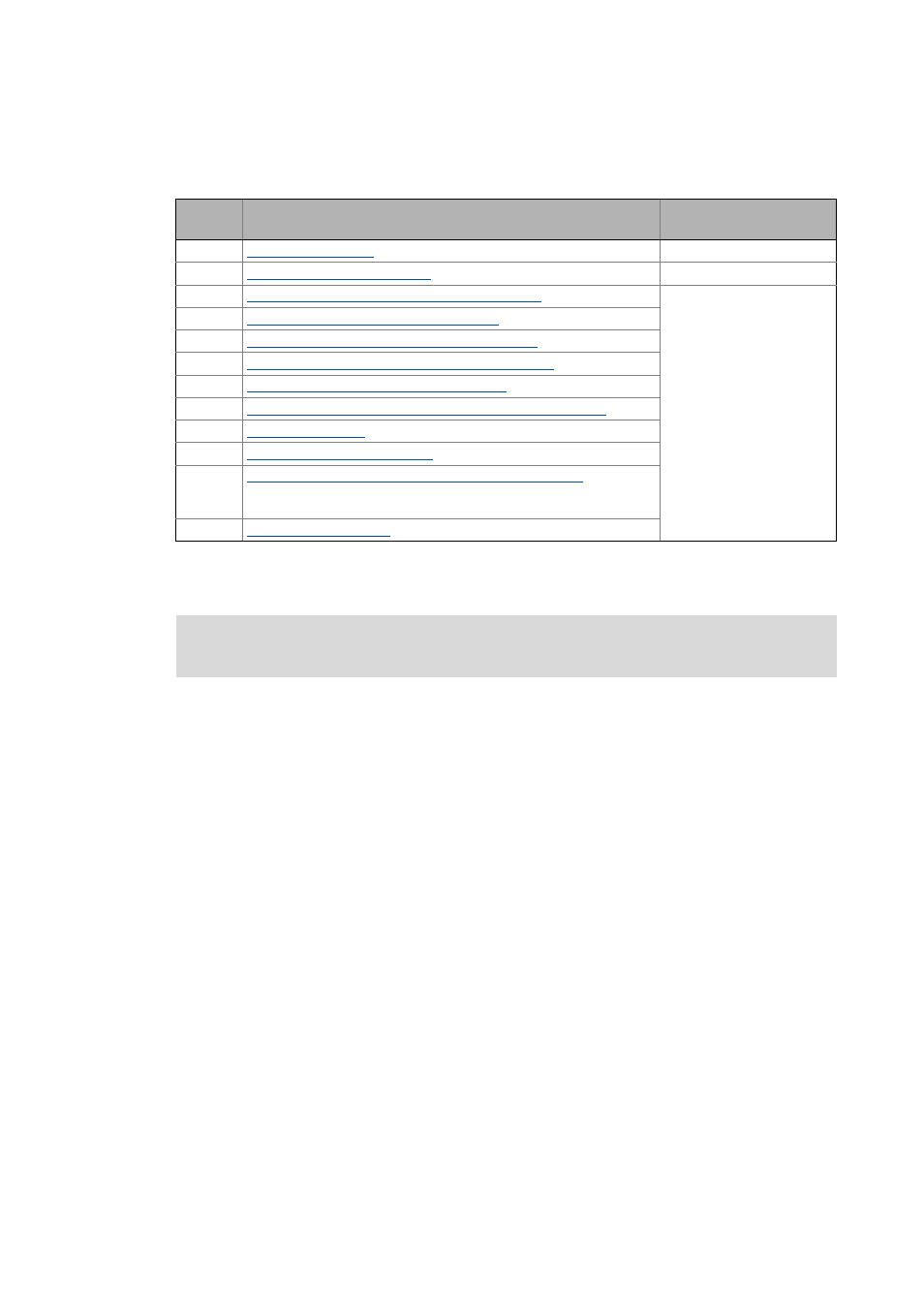
In the following sections, the individual commissioning steps are described.
Follow the instructions of these sections step by step in order to commission your system.
Step
Activity
Lenze Engineering tool to be
used
1.
Create a project folder ( 38)
2.
Commissioning the field devices ( 39)
»Engineer« / »EASY Starter«
3.
Creating a PLC program with a target system (Logic) ( 40)
»PLC Designer«
4.
Configuring the communication parameters ( 42)
5.
Importing missing devices / device description files ( 44)
6.
Creating a control configuration (adding field devices) ( 45)
7.
Setting of CAN parameters and PDO mapping ( 50)
8.
Creating the program code for controlling the Logic field device ( 57)
9.
10.
Compiling the PLC program code ( 64)
11.
Logging in on the Lenze Controller with the »PLC Designer« ( 64)
With the log-in, the fieldbus configuration and the PLC program are
loaded into the Controller.
12.
Starting the PLC program ( 64)
More detailed information about how to work with the Lenze Engineering tools can be
found in the corresponding manuals and online helps.