4 digital inputs, 5 digital outputs, 6 connection of relay output – Lenze 8400 User Manual
Page 79: Digital inputs, Digital outputs, Connection of relay output, Technical data
Technical data
StateLine C control terminals
Digital inputs
4
79
EDS84ASC552 EN 9.1
4.6.4
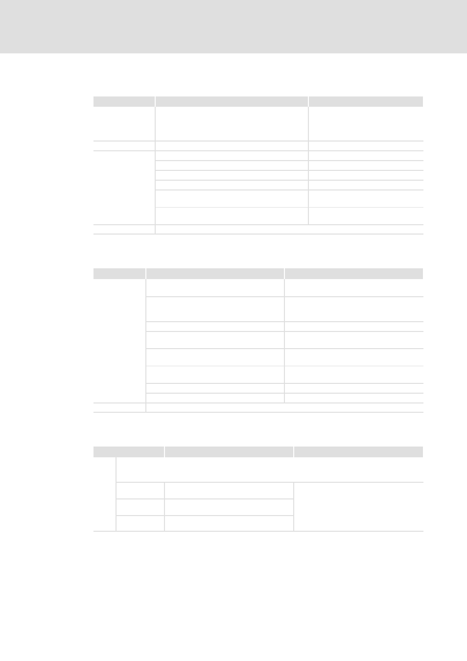
Digital inputs
Labelling
Features
Rated value
X4/DI1, DI2
Digital input 1/2
In accordance with IEC61131-2, type 1
or
two-track frequency input for HTL
encoder 0 ... 10 kHz
X4/DI3, DI4
Digital input 3/4
In accordance with IEC61131-2, type 1
X4/RFR
Controller inhibit
In accordance with IEC61131-2, type 1
Input resistance
3.3 k (2.5 k ... 6 k)
Electric strength of external voltage
Up to ±30 V, permanent
Isolation
157
Level
LOW < +5V
HIGH > +15V
Cycle time
1 ms, can be changed by software
filtering
X4/GIO
GND, reference potential for digital signals
4.6.5
Digital outputs
Labelling
Features
Rated value
X4/DO1
Digital output
In accordance with IEC61131-2, type 1, max.
50 mA
External-voltage protected
Up to +30 V
Integrated polarity reversal protection diode
for switching inductive loads
Isolation
157
Level
LOW < +5 V
High > +15 V
Time-dependent behaviour
LOW - HIGH / HIGH - LOW
Max. 250 s
Overload behaviour
Reduced voltage or periodical switch-off/on
Reset and switch-on behaviour
Outputs are switched off (LOW)
Cycle time
1 ms
X4/GIO
GND, reference potential for digital signals
4.6.6
Connection of relay output
Labelling
Description/features
Rated value
X101 In the Lenze setting, the relay switches if the controller changes to the ”Fault” device status.
Observe the notes provided in the corresponding software manual if you would like to implement
parameters other than envisaged in the Lenze setting.
COM
Relay centre contact
AC 250 V, 3 A
DC 24 V, 2 A
DC 240 V, 0.16 A
According to UL508C:
– 3 A, 250 V AC (general purpose)
– 2 A, 24 V DC (resistive)
NC
NC contact (normally closed)
NO
NO contact (normally open)