Electrical installation – Lenze 8400 User Manual
Page 183
Electrical installation
Devices in the power range 0.25 ... 2.2 kW (1/N/PE AC 230 V)
Terminal assignment of the power connections
6
183
EDS84ASC552 EN 9.1
IT system
Danger!
ƒ
The contact screws have to be removed when controllers are used in IT
operation or when external filters of E84AZESRxxxxLL or E84AZESRxxxxSD
type are used.
ƒ
When both contact screws for interference suppression are removed, the
enclosure for inverters E84AV ... will be reduced from IP 20 to IP 10.
ƒ
Pleas also observe further notes in the hardware manual and in mounting
instructions of the inverters and filters.
Tip!
You can increase the degree of protection to IP 20 again by screwing plastic
bolts made of polyamide into the open threaded holes. The thickness of the
bolt head including the washer must be greater than 3.2mm, as for example in
case of cheese head screws with internal hexagon (similar to DIN EN ISO 4762)
According to the relevant EMC product standard EN 61800-3 there are no limit values for
noise emission in the high-frequency range. Therefore, the technical data for EMC do not
apply.
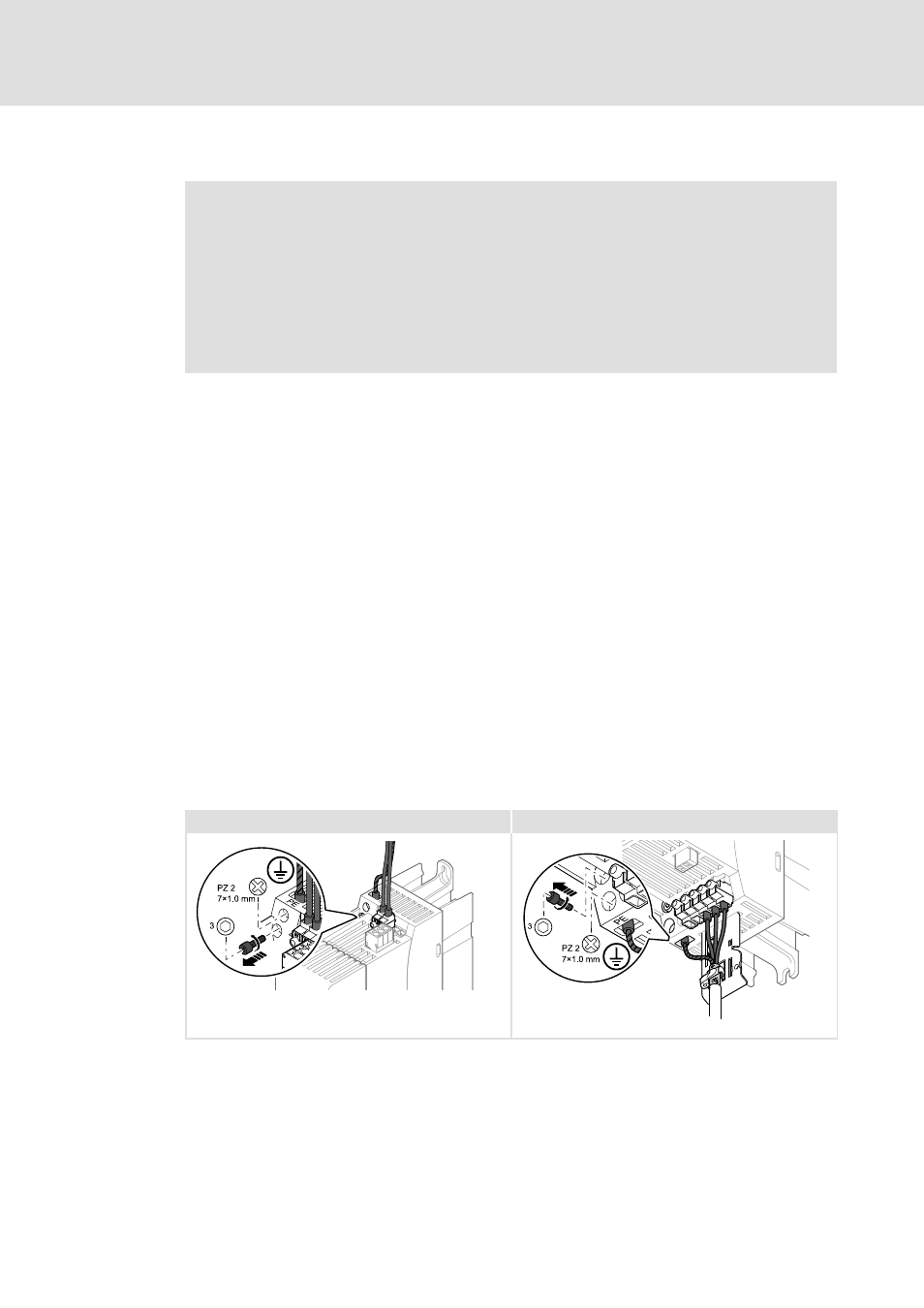
Before using the controller in the IT system, remove both contact screws for interference
suppression:
– Two hexagon socket screws M4 x 16 mm with washers.
– Insert for Allen key: 3mm
The tightening torque of the contact screws for connecting the drive to other networks is
1 Nm (8 Ib-in).
X100 - IT
X105 - IT
8400GG002
8400GG014
Fig. 6-14
Removal of the contact screws for device sizes 1 ... 3 (on the supply side and on the motor side)