Product description – Lenze 8400 User Manual
Page 24
Product description
Overview of control terminals
3
24
EDS84ASC552 EN 9.1
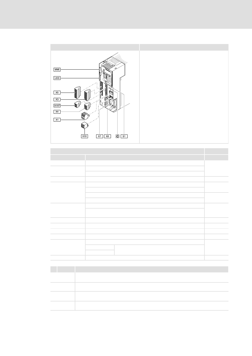
Control terminals for devices in the TopLine version
8400TLC032b
Connection
Information
Pos.
Description
TopLine C
X1
CANopen connection
213
S1
CANopen settings
Settings for CANopen terminating resistor and axis bus
X3
Analog inputs / outputs; 10 V reference voltage
230
X4
Digital inputs; controller enable
-
24 V supply of the control electronics
Digital outputs
234
234
24 V voltage output
X5
Digital inputs; controller enable
233
External 24 V supply of the control electronics; internal 24 V supply, fused
via PTC
X6 (DIAG)
Diagnostic interface
221
X7
Resolver
237
X8
Encoder
238
X10
Axis bus
239
X107
24 V brake supply
236
+ BD1
Connection for DC brake coil
- BD2
MMI
Slot for memory module (Memory Module Interface)
293
Icon
Description
Long discharge time: All power terminals remain live for a few minutes after mains
disconnection! The duration is given under the warning symbol on the device.
High leakage current: Carry out fixed installation and PE connection according to EN 61800-5-1!
Electrostatic sensitive devices: Before working on the device, the personnel must be free of
electrostatic charge!
Hot surface: Risk of burns! Hot surfaces should not be touched without wearing protective
gloves.