Electrical installation, Stateline: stripping dimensions, Highline: stripping dimensions – Lenze 8400 User Manual
Page 211: Topline: stripping lengths
Electrical installation
Common control terminals
Important notes
6
211
EDS84ASC552 EN 9.1
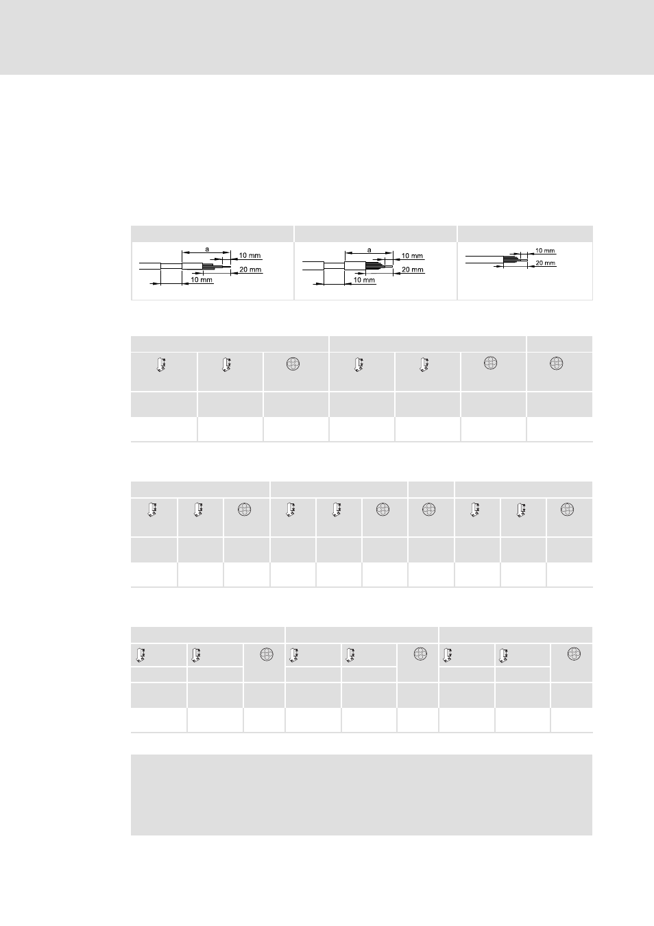
Strip cables
According to the selected lock-in position of the shield sheet, strip the control cables. For
this, strip the cable ends and the cable sheath at the shield lug.
The following table shows the stripping length for the control cables depending on the
selected lock-in position of the shield sheet.
X1
X3, X107
X4, X5
;
;
84MOTL001_e
84MOTL001_d
84MOTL001_f
ƒ
StateLine: stripping dimensions
X1
X3
X4
min.
max.
min.
max.
a
[mm]
a
[mm]
[mm
2
]
[AWG]
a
[mm]
a
[mm]
[mm
2
]
[AWG]
[mm
2
]
[AWG]
110
135
0.2 ... 1.5
24 ... 16
150
175
0.2 ... 1.5
24 ... 16
0.2 ... 1.5
24 ... 16
ƒ
HighLine: stripping dimensions
X1
X3
X4, X5
X107
min.
max.
min.
max.
min.
max.
a
[mm]
a
[mm]
[mm
2
]
[AWG]
a
[mm]
a
[mm]
[mm
2
]
[AWG]
[mm
2
]
[AWG]
a
[mm]
a
[mm]
[mm
2
]
[AWG]
110
135
0.2 ... 1.5
24 ... 16
150
175
0.2 ... 1.5
24 ... 16
0.2 ... 1.5
24 ... 16
115
140
0.2 ... 1.5
24 ... 16
ƒ
TopLine: Stripping lengths
X1
X3/X5
X4/X107
min.
max.
min.
max.
min.
max.
a
a
a
a
a
a
[mm]
[mm]
[mm
2
]
[AWG]
[mm]
[mm]
[mm
2
]
[AWG]
[mm]
[mm]
[mm
2
]
[AWG]
110
135
0.2 ... 1.5
24 ... 16
150
175
0.2 ... 1.5
24 ... 16
115
140
0.2 ... 1.5
24 ... 16
Note!
Devices including safety engineering have an increased stripping length ”a”:
ƒ
by 10 mm when the shield sheet is pulled out to its minimum length
ƒ
by 15 mm when the shield sheet is pulled out to its maximum length