Braking operation, Stop, Operation with spring-applied brake introduction – Lenze 8400 User Manual
Page 259: Connection +/-), Set u
Braking operation
Operation with spring-applied brake
Introduction
8
259
EDS84ASC552 EN 9.1
Stop!
Requirements with regard to the brake cable (connection BD1/BD2):
ƒ
Brake cables must be shielded if they are incorporated in the motor cable.
– Operation with unshielded brake cables can destroy the motor brake
control.
– We recommend the use of Lenze system cables (motor cable with
separately shielded additional cores).
ƒ
In the case of a permanent magnet holding brake, observe the correct
polarity of the brake cable.
– If the terminals are inverted, the brake does not release. As the motor is
running against the closed brake, the brake can be destroyed.
ƒ
Apply the shield to PE on both sides.
Requirements with regard to the supply voltage U
DC
(connection +/-):
ƒ
Always supply the motor brake control with a separate 24 V supply.
– A common supply of the motor brake control and the controller control
card is not permissible, as otherwise the basic insulation between the two
components is reduced.
ƒ
Set U
DC
so that the operating voltage of the brake is within the permissible
range and the maximum supply voltage of the motor brake control is not
exceeded.
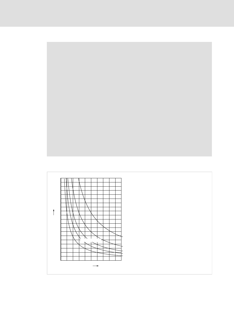
Cable length
0
0.5
1
1.5
2
2.5
3
3.5
4
4.5
5
I
Br
[A]
0
20
40
60
80
100
120
140
160
180
200
L
max
[m]
0.5 mm
2
(AWG 20)
0.75 mm
2
(AWG 18)
1 mm
2
(AWG 16)
U
DC
= 24 V DC
1.5 mm
2
(AWG 14)
2.5 mm
2
(AWG 12)
E94AZHY004
L
max
Maximum brake cable length in [m]
I
BR
Brake current in [A]
U
DC
Supply voltage of the motor brake control