Electrical installation – Lenze 8400 User Manual
Page 201
Electrical installation
Devices in a power range of 30 ... 45 kW (3/PE AC 400 V)
Terminal assignment of the power connections
6
201
EDS84ASC552 EN 9.1
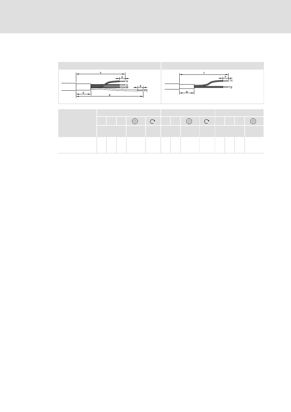
Strip cables
X105
X106
;
;;
;
84MOTL001_a
84MOTL001_b
U, V, W
PE
T1, T2
b
c
e
a
d
f
g
h
[mm]
[mm
2
]
[AWG]
[Nm]
[lb-in]
[mm]
[mm
2
]
[AWG]
[Nm]
[lb-in]
[mm]
[mm
2
]
[AWG]
E84AVxxx3034
E84AVxxx3734
E84AVxxx4534
40 190 24 16 ... 50
6 ... 0
4.0
35
250 16 2.5 ... 25
12 ... 2
4.0
35
240 40 10 0.2 ... 1.5
24 ... 16
How to proceed:
1. Strip motor cable and cable for motor temperature monitoring according to
specified dimensions.
2. Fold back the shield of the motor cable and motor temperature cable over the cable
sheath. Keep unshielded ends short.
3. Fix shield on the cable sheath (e.g. using a heat-shrinkable tube).
4. Fasten wire end ferrule to PE cable.
– The other cables may be wired without using wire end ferrules.
5. Connect the shields separately to the shield sheet using (metal) cable ties or shield
clamps.
– left: motor cable
– right: cable of motor temperature monitoring
– For strain relief of the cables, measures are required.