3 overview of control terminals, Product description – Lenze 8400 User Manual
Page 23
Product description
Overview of control terminals
3
23
EDS84ASC552 EN 9.1
3.3
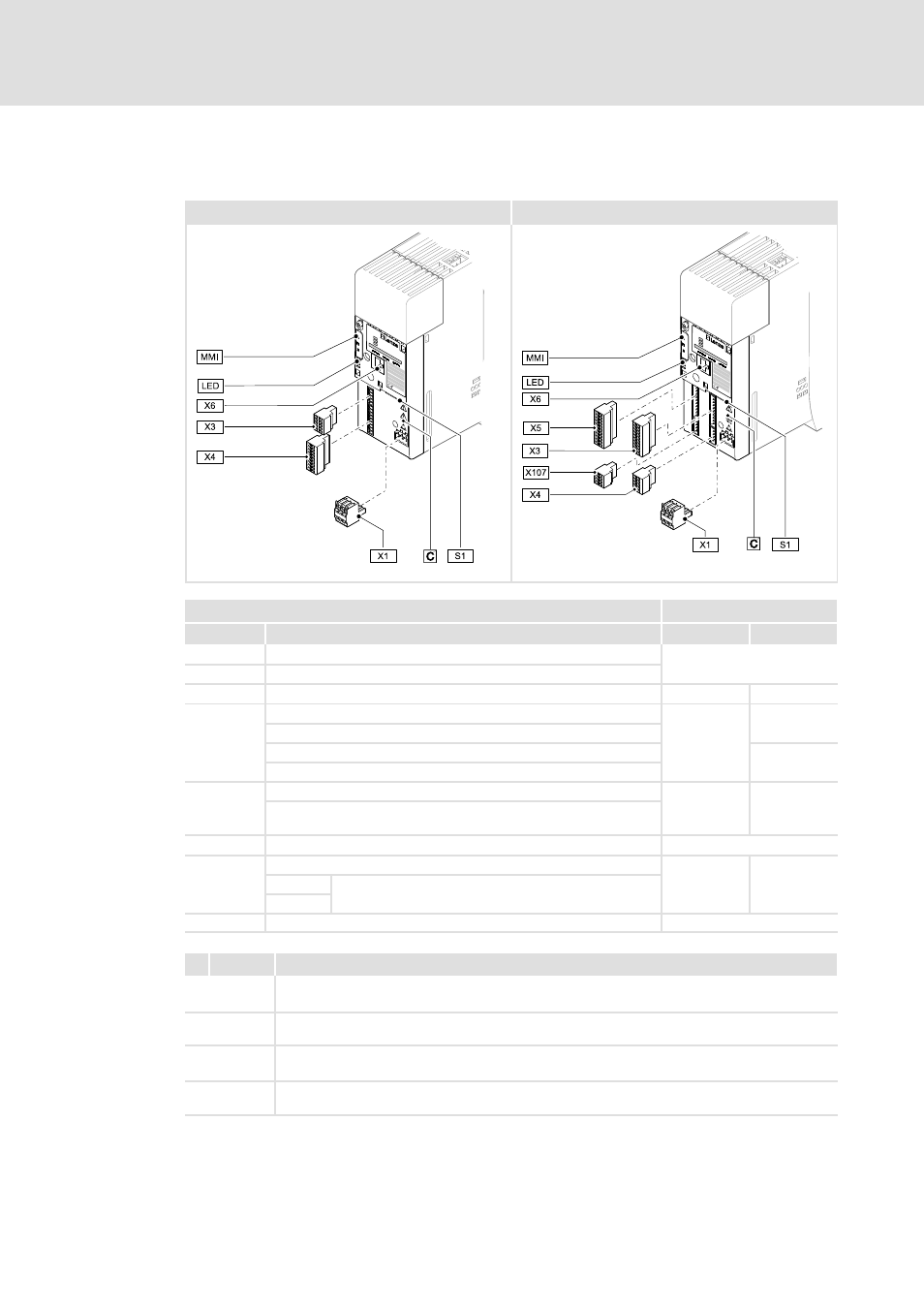
Overview of control terminals
Control terminals for devices in the StateLine version
Control terminals for devices in the HighLine version
8400HLC080a
8400HLC081a
Connection
Information
Pos.
Description
StateLine C
HighLine C
X1
CANopen connection
213
S1
CANopen settings
X3
Analog inputs/outputs; 10V reference voltage
223
230
X4
Digital inputs; controller enable
234
-
24 V supply of the control electronics
Digital outputs
234
24 V voltage output
X5
Digital inputs; controller enable
-
233
External 24V supply of the control electronics; internal 24V supply
fused via PTC
X6 (DIAG)
Diagnostic interface
221
X107
24 V brake supply;
-
236
+ BD1
Connection for DC brake coil
- BD2
MMI
Slot for memory module (Memory Module Interface)
293
Icon
Description
Long discharge time: All power terminals remain live for a few minutes after mains
disconnection! The duration is given under the warning symbol on the device.
High leakage current: Carry out fixed installation and PE connection according to EN 61800-5-1!
Electrostatic sensitive devices: Before working on the device, the personnel must be free of
electrostatic charge!
Hot surface: Risk of burns! Hot surfaces should not be touched without wearing protective
gloves.