Nanodac – Carbolite nanodac User Manual
Page 99
nanodac™
97
MC27 –EN–1.04
Table 6.4.7 Calculate parameter values
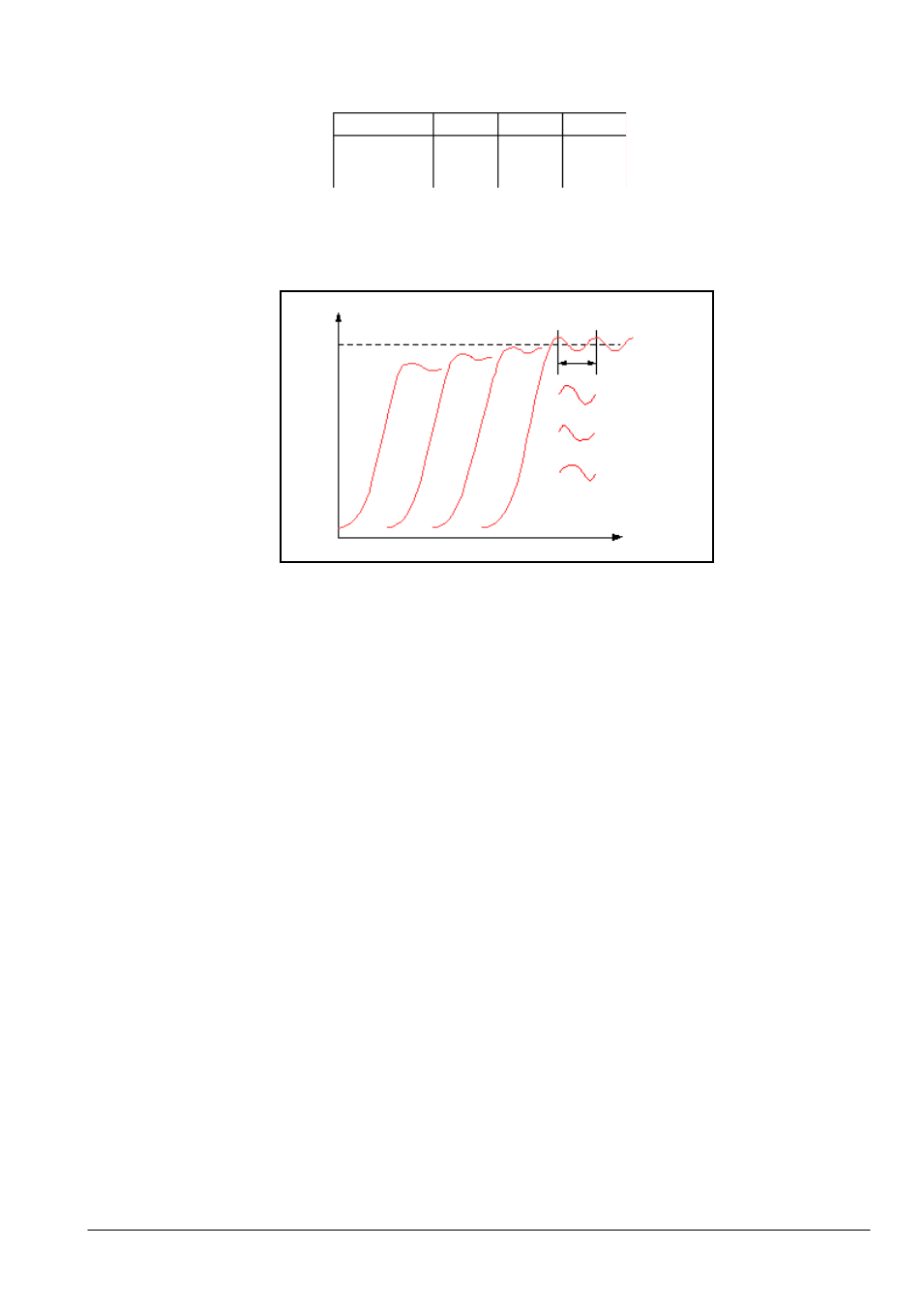
Figure 6.4.6a Relative Cool Gain
CUTBACK VALUES
The PID terms calculated from Table 6.4.7, above, should be entered before the cutback values are set.
The above procedure sets up the parameters for optimum steady state control. If unacceptable levels of
overshoot or undershoot occur during start-up, or for large step changes in PV, then the cutback
parameters should be set manually, as follows:
1.
Initially set the cutback values to one proportional bandwidth converted into display units. This can
be calculated by taking the value in percent that has been installed into the parameter ‘PB’ and
entering it into the following formula:
PB/100
Span of controller = Cutback High and Cutback Low
For example, if PB = 10% and the span of the controller is 0 to 1200°C, then
Cutback High = Cutback Low = 10/100
1200 = 120
Control type
PB
Ti
Td
Prop ortional only
P + I
P + I + D
2
PB
′
2.2
PB
′
1.7
PB
′
Off
Off
0.12
T
Off
0.8
T
0.5
T
Setpoint
R2G correct
R2G too large
R2G too small
Time
Te
m
p
er
atu
re