Group configuration, Group trend configuration, Nanodac – Carbolite nanodac User Manual
Page 60: 2 group configuration
nanodac™
MC27 –EN– 1.04
58
= 8; Number of stop bits = 1; no flow control. Can be set to ‘Modbus Slave’ or ‘Off’.
The unit must be restarted before any change takes effect.
Time Format
Allows the user to choose milliseconds, seconds, minutes or hours as the time
format. Sets the resolution for the reading and writing of time format parameters.
PrefMaster Conn
Read only. Shows the IP address of the preferred master, when connected.
Response Time
Read only. Shows the response time for a single communications request to the
relevant master.
Master Conn 1 to 4
Read only. Shows the IP addresses of any other masters connected to this
recorder.
5.2 GROUP CONFIGURATION
Group configuration is separated into two areas, one which defines trending characteristics (for display
channels) the other defining the recording characteristics for saving data to the Flash memory ready for
archiving.
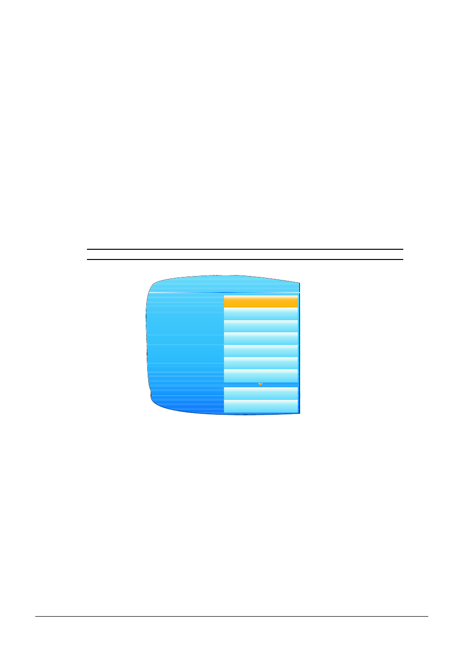
5.2.1 Group Trend configuration
This allows the user to define which points are to be traced on the display and at what interval, and also
allows the number of chart divisions to be set up. Figure 2.3.1 shows a typical configuration page.
Note: The background chart colour is set up as a part of Instrument Display configuration.
Figure 2.3.1 Group Trend Configuration
Descriptor
Allows the user to enter a descriptor (20 characters max.) for the group.
Interval
The trending interval which defines how much data appears on one screen height
or width. A number of discrete intervals can be chosen between 0.125 seconds to 1
hour. The selection should be made according to how much detail is required, and
how much data is to be visible on the screen.
Major Divisions
Allows the user to select the number of divisions into which the scale is divided and
how many gridlines are displayed. Setting the value to 1 results in just the zero and
full scale values appearing. Setting the value to 10 (the maximum) results in a scale
with zero, full scale and nine intermediate values appearing, with associated grid
lines.
Point1 to Point6
Allows the user to select which channels and virtual channels are to be traced. The
maximum number of traces is six.
Descriptor
Interval
Major Divisions
Point1
Point2
Point3
Point4
Group.Trend
Group 1
0.25 sec
10
Channel1
Channel2
Channel3
Channel4
Point5
Point6
No Trend
VirtualChan1