Alarm panel, Nanodac – Carbolite nanodac User Manual
Page 27
nanodac™
25
MC27 –EN–1.04
Figure 1.4.5a Numeric display mode (six enabled channels)
The figure above shows an example where the Trend group contains six channels. Figure 1.4.5b shows
how the display appears for trend groups with fewer than six channels configured.
Figure 1.4.5b Display layout for different numbers of channels
The up arrow button returns to the vertical trend display mode; the page key calls the top level menu.
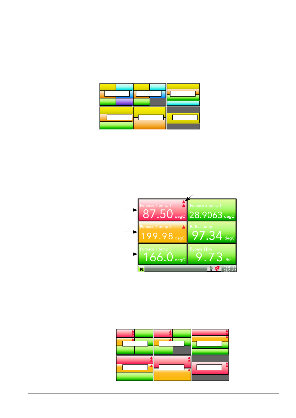
4.4.6 Alarm panel
This display appears only if enabled in the Instrument Display configuration. Alarm panel mode shows
current value and alarm status for each channel enabled in the Trend Group. The status is shown in two
ways, by the colour of the relevant bar, and by the alarm status indicators.
Figure 1.4.6a Alarm panel display (six channels)
The figure above shows an example where the Trend group contains six channels. Figure 1.4.6b shows
how the display appears for trend groups with fewer than six channels configured.
6 channels
5 channels
4 channels
3 channels
2 channels
1 channel
6 channels
5 channels
4 channels
3 channels
2 channels
1 channel
Red bar
Alarm 2 is active, or alarm 1 and
alarm 2 are both active.
Amber bar
Alarm 1 is active for this
channel, but not alarm 2
.
Green bar
Neither alarm 1 nor alarm two
active for this channel.
.
Alarm type indication (table 3.2.1)