Promote list, Nanodac – Carbolite nanodac User Manual
Page 41
nanodac™
39
MC27 –EN–1.04
PROGRAM LOAD VIA A PROGRAM NUMBER
This feature has been added to firmware versions V5.00 and above.
To allow a program (stored as a file) to be loaded, either via a BCD switch, wired to a set of digital inputs,
or via a single comms transaction, it is necessary to prefix the progam name with a program number in
the range 01 to 99. For example, 01kiln1.uipz, 01furnace.uipz, 02kiln2.uipz, 03kiln3.uipz etc. The
program name can consist of up to 18 characters. Note that program numbers 1 to 9 must be entered as
01 to 09 otherwise they will not be recognised by the switch or via comms.
On value change of the program number, the first program file with the prefixed number in the
instrument’s internal User drive (listed lexographically) will be loaded. In the above example if program 01
is selected, 01furnace.uipz will be loaded, 01kiln1.uipz will not be loaded using the BCD switch or through
comms. It can, of course, be loaded manually.
If no program number is prefixed it is not possible to load the program via the BCD switch or via comms.
It is, however, still possible to load the program by selecting the file as described in the previous section.
Note: When a BCD switch is turned from its current value to another value, intermediate switch positions
may be seen on the inputs of the BCD function block and could potentially be used by subsequent blocks
wired from the BCD input. A Settle Time parameter has been introduced which will in effect filter out
these intermediate values by applying a time in which the inputs can settle before their converted decimal
value is seen on the output parameters of the block. The Settle Time can be set from 0-10seconds with a
default of 0s i.e. no filtering as in previous firmware versions.
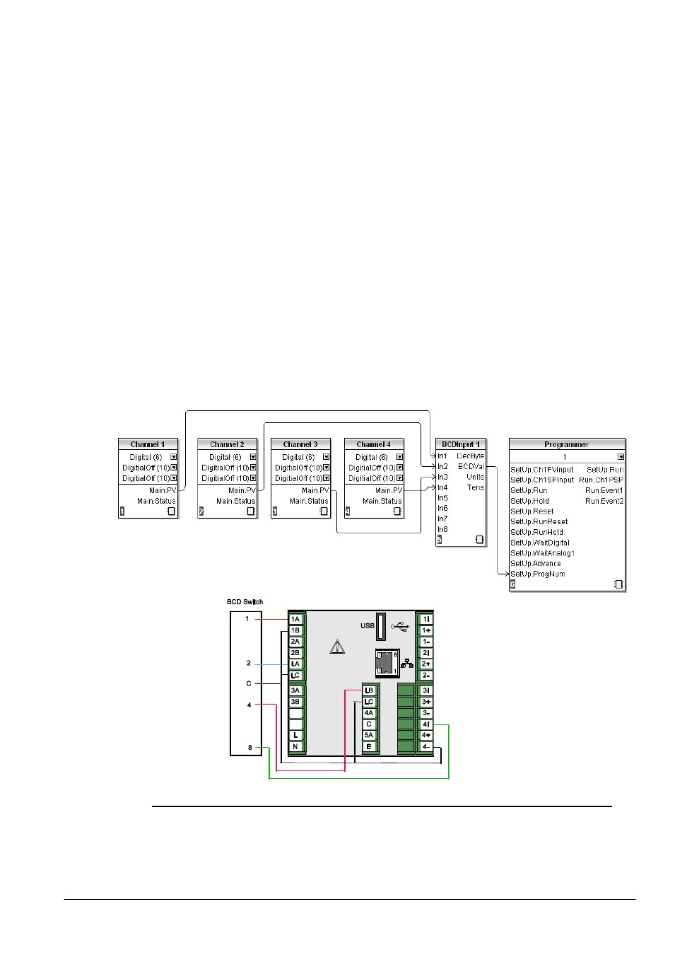
EXAMPLE BCD SWITCH WIRING
Figure 1.4.9l below shows an example of using digital input channels soft wired to the BCD function block
using iTools.
Figure 1.4.9l BCD Switch Wiring
Figure 1.4.9m below shows the corresponding hard wiring of a BCD switch.
Figure 1.4.9m BCD Switch Physical Wiring
4.4.10
Promote List
This display page allows the user to display up to 10 of the parameters that appear anywhere in the
operator interface. The parameters can be selected only by using iTools, as described below.
Notes:
1. ‘Promote List’ must be enabled (in ‘
Instrument.Display
’ configuration), before it appears in the
‘Go to View’ list.
2. There are more parameters visible in iTools than appear at the operator interface. If non-
operator interface parameters are selected for inclusion in the promote list, they do not
appear.