Nanodac – Carbolite nanodac User Manual
Page 85
nanodac™
83
MC27 –EN–1.04
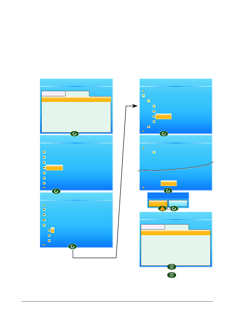
Counter Example (Cont.)
8.
Operate the Scroll key to highlight ‘Add new wire’, then again to display the top level parameter list.
9.
Use the down arrow button to highlight ‘Channel’ and operate the scroll button.
10. Operate the scroll button to select ‘1’.
11. Highlight ‘Alarm 1’ and operate the scroll button.
12. Use the down arrow button to highlight ‘Active’. Operate the Scroll button again, and create the new
wire.
13. Use the Page button twice to return to the Virtual Channel 3 menu.
Figure 4.2b Wiring a counter: part 2
User Wiring
User Wiring
From source
To destination
Add new wire
Channel
1
Main
Trend
Alarm1
Alarm2
Virtual Channel.3.Main.Trigger
Virtual Channel.3.Main.Trigger
User Wiring
Virtual Channel.3.Main.Trigger
User Wiring
Virtual Channel.3.Main.Trigger
User Wiring
Virtual Channel.3.Main.Trigger
User Wiring
Virtual Channel.3.Main.Trigger
Instrument
Network
Group
Channel
Virtual Channel
Loop
Digital I/O
Alarm1
Create New Wire
Cancel
OK
Instrument
Network
Group
Channel
1
2
3l
From source
To destination
Add new wire
Channel.1.Alarm1.Active
Type
Status
Threshold
Dwell
Acknowledge
Active