Nanodac – Carbolite nanodac User Manual
Page 46
nanodac™
MC27 –EN– 1.04
44
Ethernet/IP Display Mode (Cont.)
If the EtherNet/IP option has been ordered and enabled, the nanodac can be configured as either a client
(master) or a server (slave)
. The client and server displays are identical except that the configuration area
of the client display is more extensive than that of the server display.
Figure 1.4.13a, above shows a typical set of display pages for an EtherNet/IP client.
CONFIGURATION OF IMPLICIT INPUT/OUTPUT TABLES
Configuration of the input and output tables is carried out via iTools drag and drop only by:
a.
Entering the parameters to be read by the client into the server output table.
b
Entering the destination parameter into the equivalent location in the client input table.
c.
Entering the parameters to be written by the client into the client output table.
d
Entering the destination parameter into the equivalent location in the server input table.
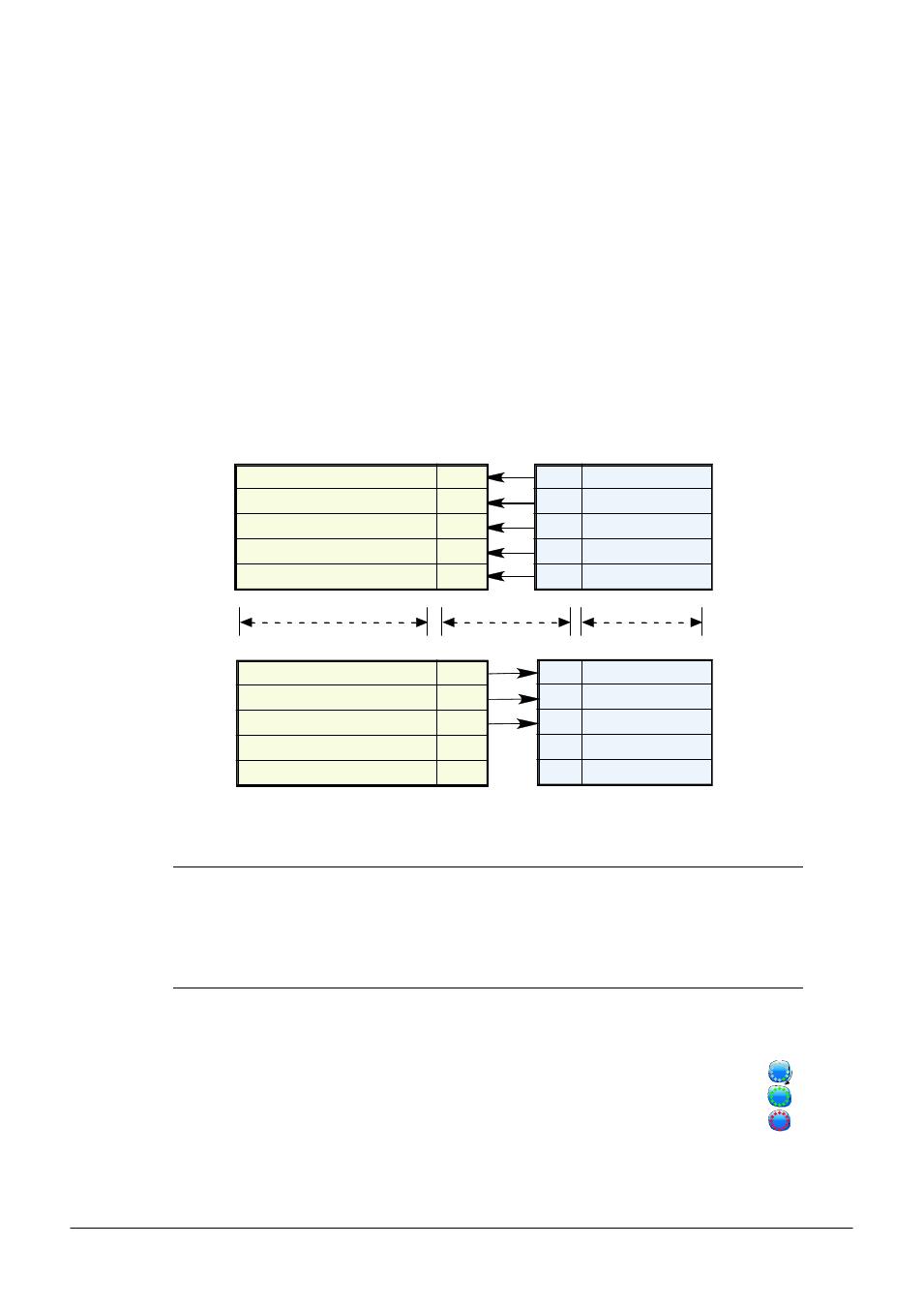
The example in figure 1.4.13b attempts to show this (using the nanodac as the client) in graphical form,
using just a few parameters (there can be up to 50 in each table)
Figure 1.4.13b Input/Output table entries
Notes:
1. Channel values from the Server can be ‘wired’ into nanodac Virtual channel inputs (as shown
above) so that they can be traced and/or recorded. In such cases the virtual channel
‘Operation’ must be set to ‘Copy’.
2. Inputs and outputs would normally be given suitable descriptors (e.g. ‘Reset timer’ instead of
‘Channel.1.Alarm1’).
CONNECTION STATUS INDICATOR
A circular status indicator appears in a number of the EtherNet/IP display pages. This indicator can
indicate the following states:
Green rotating ‘flash’: the instrument is on line and at least one CIP connection is established.
Green flashing circle: the instrument is on line but no CIP connections have been established.
Red flashing circle: there is a break in the physical connection between the client and the server, or the
remote unit is switched off or is initialising.
Client (nanodac) input table
Virtual Channel.1.Main.Input1 I/P
Virtual Channel.2.Main.Input1 I/P
Virtual Channel.3.Main.Input1 I/P
Virtual Channel.4.Main.Input1 I/P
etc.
Server output table
O/P1
O/P2
O/P3
O/P4
etc.
Out Parameter 1
Out Parameter 2
Out Parameter 3
Out Parameter 4
Client (nanodac) output table
User Values.1.Value
Channel.1.Alarm1
Server) input table
I/P1
I/P2
etc.
In Parameter 1
In Parameter 2
O/P1
O/P2
etc.
Input Data
Destination
The implicit data
value coming in
from the
EtherNet/IP
device will be
copied to this
wired parameter
Output Data
Source
The value coming
in from this wire
will be sent to the
EtherNet/IP
device.
Output Data
Source
The value
coming in
from this wire
will be sent to
the
EtherNet/IP
device.
Wired parameters
Values
Wired parameters