Control loop1/loop2, Nanodac – Carbolite nanodac User Manual
Page 28
nanodac™
MC27 –EN– 1.04
26
Figure 1.4.6b Alarm panel display layouts for trend groups with fewer than six channels
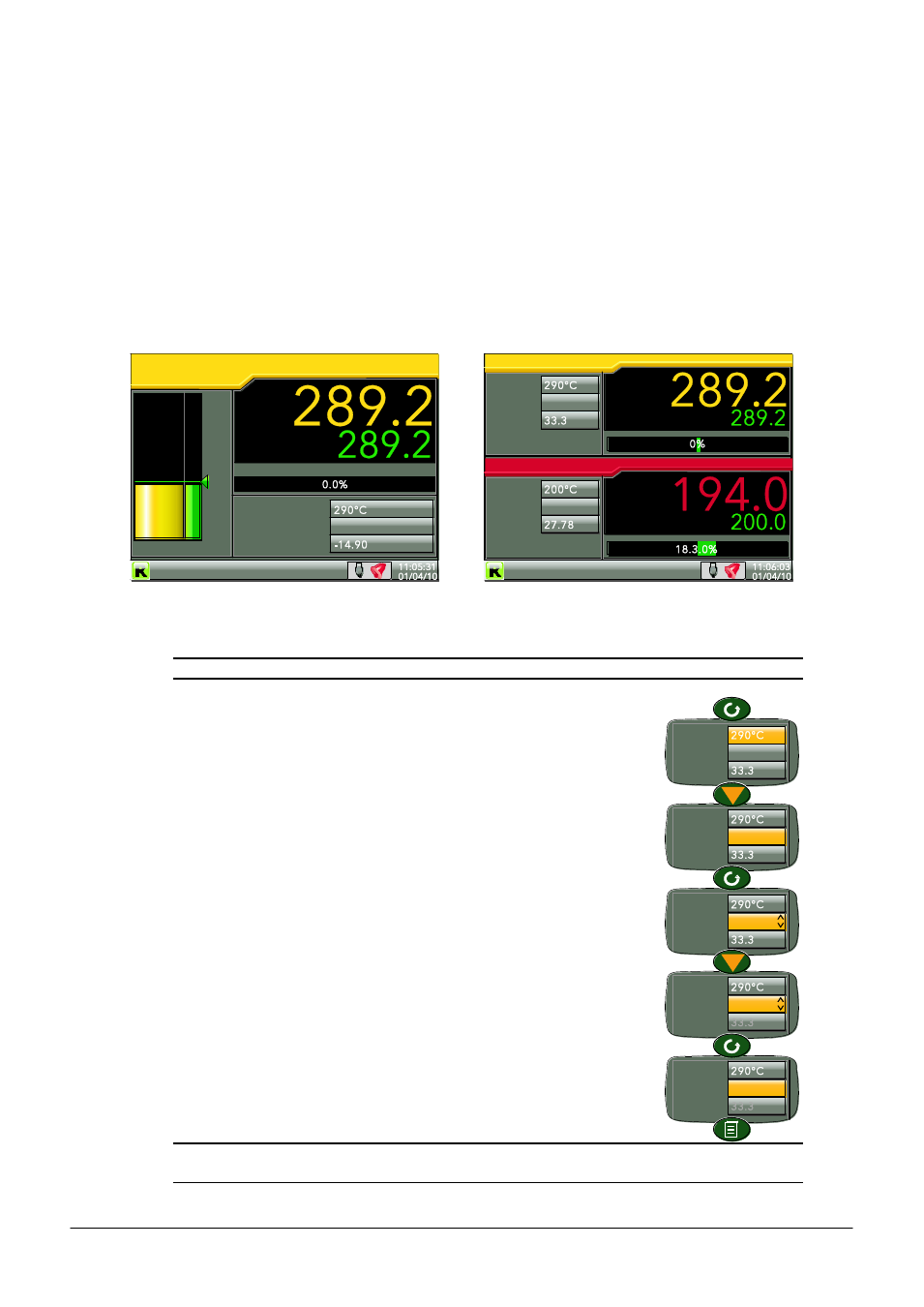
4.4.7 Control Loop1/Loop2
These displays appear only if the controller option is enabled.
The loop display modes are interactive, in that the setpoint, the Auto/Manual mode and the Manual
Output value can be edited from the user interface. Full configuration is carried out in the Loop setup
menus and a fuller description of control loops is to be found as
Appendix B
to this manual.
Figure 1.4.7 depicts a single loop display and the dual loop display. The up and down arrow keys are used
as normal to scroll through Loop1, Loop2 and Dual loop pages.
Figure 1.4.7 Loop displays
Note: The colours associated with the loops are those of the channels to which they are wired.
EDITING TECHNIQUES
1.
With the loop page on display, operate the Scroll key. This highlights the
first editable item (SP1). The scroll order includes both loop1 and loop 2
parameters in the dual loop display.
2.
Use the up and down arrow keys to select the required field for editing.
When the required field is highlighted, operate the scroll key again, to
enter edit mode.
3.
Use the up/down arrows to edit the current setting.
4.
Operate the scroll key to confirm the edit.
5.
Select a further parameter for editing, or operate the page key to return
to normal operation.
Note: Edit permissions for Setpoint, Auto/Manual and Manual Output Access are set in the Loop
Setup configuration menu.
PV
wSP
Working Output
SP
SP1
Mode
Ma
n
OP
PV
wSP
SP1
Mode
Man OP
SP1
Mode
Man OP
Loop 1
O
C
Loop 1
Manual
PV
wSP
Manual
Inst name
Inst name
SP1
Mode
Man OP
SP1
Mode
Man OP
SP1
Mode
Man OP
SP1
Mode
Man OP
SP1
Mode
Man OP