Nanodac – Carbolite nanodac User Manual
Page 47
nanodac™
45
MC27 –EN–1.04
Ethernet/IP Display Mode (Cont.)
Adding parameters to the input and output tables can be achieved only through the proprietary software
package ‘iTools’, running on a pc. It cannot be configured through the user interface. The following
description assumes that the user is familiar with ‘iTools’. Section 6 of this manual shows how to set up an
iTools link to the unit and the iTools on-line help system and its pdf version (HA028838) should be
referred-to as necessary.
Note: the client/server and the pc must all be on the same network.
Once iTools has started up and the ‘Scan’ process has ‘found’ the relevant
instrument, the scan process should be stopped and the instrument (s)
allowed to synchronise. (The scan may be left to run its course, but the speed
at which iTools operates is reduced for the duration of the scan process.)
EXAMPLE
To add Loop 2 Setpoint 2 to Output 4 of the Client Output table.
In the example shown below, the instruments have both synchronised,
and the ‘Access’ tool button clicked-on for both instruments to set them
into configuration mode.
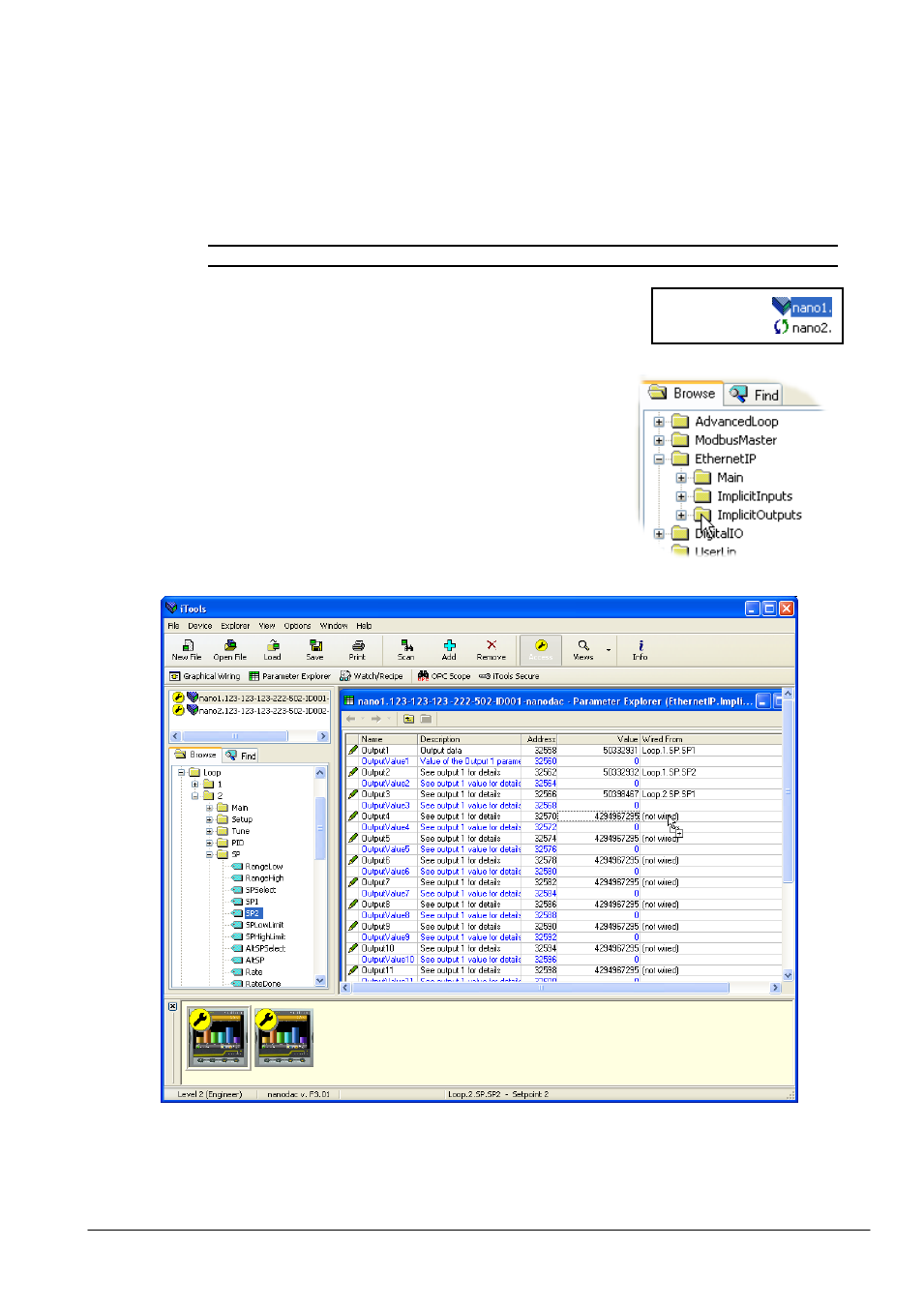
With the client selected, expand the EtherNet/IP folder in the Browse
list, then double-click on the ‘ImplicitOutputs’ folder.
Locate and expand the Loop 2 SP folder in the Browse window, and
click-drag SP2 to ‘Output 4’ and release.
Figure 1.14.3c Dragging a parameter to the Output table
Synchronised
Not Synchronised