Operation, Introduction, Display screen – Carbolite nanodac User Manual
Page 9: Navigation pushbuttons, Nanodac
nanodac™
7
MC27 –EN–1.04
4. OPERATION
On power up a default or custom splash screen appears and remains visible whilst the
unit is initialising. If during this process a network broadcast storm is detected, the
unit stops, displaying a network failure icon until the broadcast storm has cleared,
after which the initialisation process resumes.
4.1 INTRODUCTION
The operator interface consists of a display screen and four push buttons.
4.1.1 Display Screen
The display screen is used both to display channel information (in one of a number of display modes), and
to display the various configuration screens which allow the user to setup the recorder to display the
required channels, to set up alarms and so on. Display modes are described in Section 4.4 below;
configuration is described in Section 5
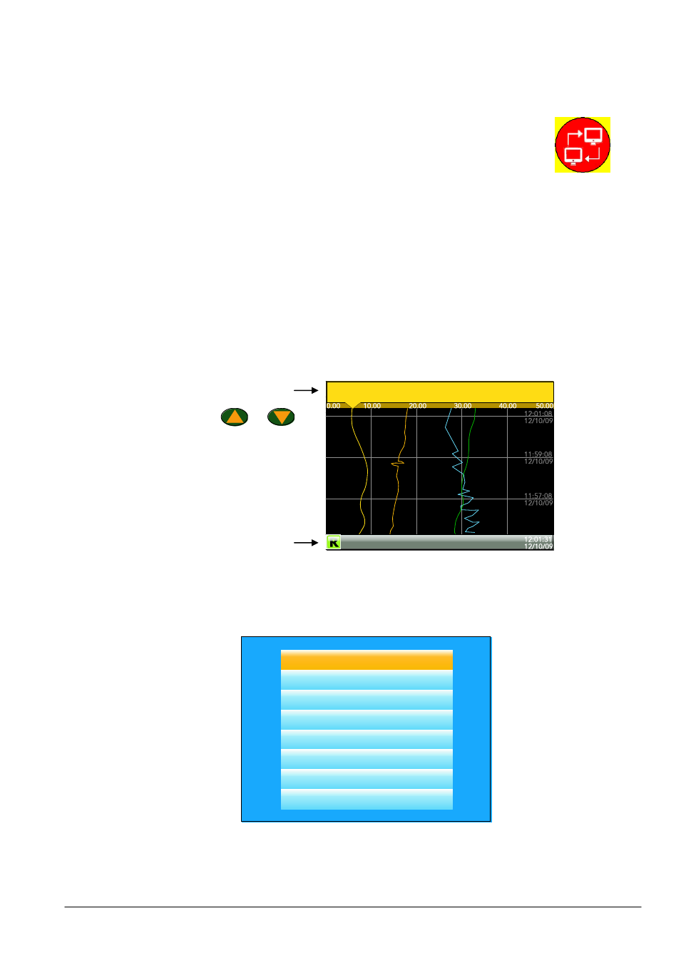
In display mode, the screen is split horizontally into three areas (figure 1.1.1)
1.
a faceplate giving channel details.
2.
the main display screen showing channel traces etc.
3.
the status area, displaying instrument name, the current time and date and any system icons.
Figure 1.1.1 Display mode screen (vertical trend)
In configuration mode, the entire display screen is devoted to the selected configuration menu.
4.1.2 Navigation Pushbuttons
Figure 1.1.2 Top level menu (Engineer level access)
There are four navigation buttons, called ‘Page’, ‘Scroll’, ‘Lower’ and ‘Raise’ located below the screen. The
general properties of these buttons are described in the remainder of this section, but some have
additional, context sensitive functions, which, for the sake of clarity are not described here but in the
relevant sections (e.g. ‘Message summary’) of the manual.
Faceplate
Main display
screen
Status area
Home
Configuration
Go to View
History
Faceplate Cycling (On)
Operator Notes
Demand Archiving
Log Out