Allied Telesis AT-VIEW PLUS 3.2 DEVICE MANAGEMENT User Manual
Page 210
Allied Telesyn
AT-VIEW PLUS
DEVICE MANAGEMENT
AT-9748TS/XP AT-9724TS
7
<=2
6
<=4
5
<=6
4
<=8
3
<=9
2
<=10
1
<=11
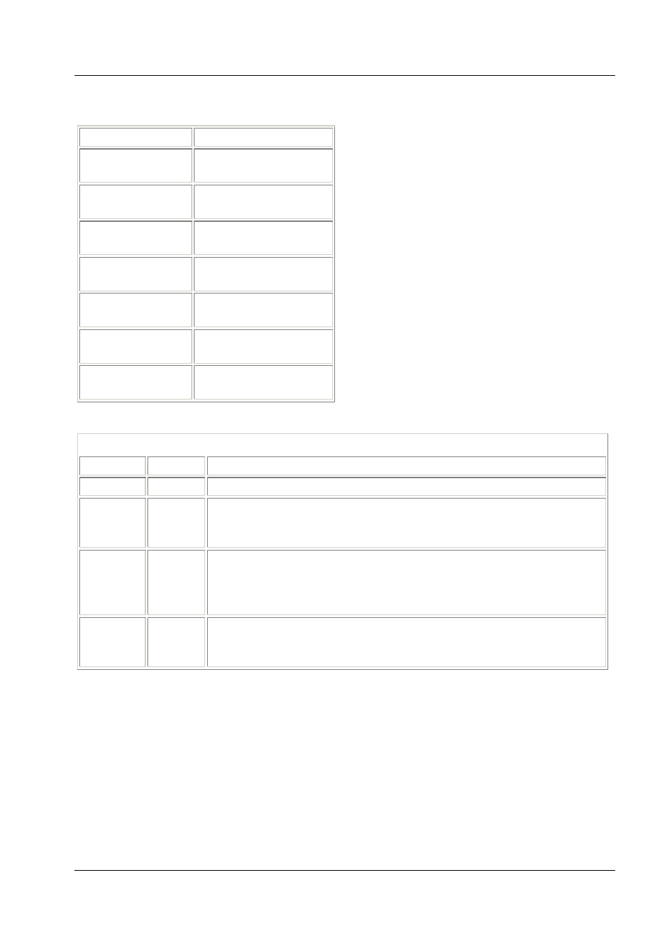
Device Manager LEDs for AT-9700 Series
LED
State
Description
PWR
Green
The switch is receiving power from the main power supply.
RPS
Green
Gray
The switch is receiving power from the redundant power supply.
RPS is not installed or not functioning.
STACK ID Green
Orange
The stacked unit is either a slave switch or the switch is not in a stacked
mode.
The stacked unit is the master switch.
DUPLEX Green
Orange
The port is operating in full-duplex mode.
The port is operating in half-duplex mode.
Note
- The Stack ID LED indicates the Box ID of the stacked switch or standalone switch.
Note
- The current firmware version does not allow AT-View Plus Device Manager to detect the
presence or absence of an SFP module in any of the SFP slots. As a result, the SFP slots on the
device image will always show SFP images regardless of whether or not SFP modules are
physically present in the slots.
Note
- Status information for ports 21 to 24 on the AT-9724TS and ports 45 to 48 on the AT-
9748TS/XP will always be reflected on both the RJ-45 port images and the SFP port images
regardless of whether it is the RJ-45 or the SFP ports that are actually in operation. However, if
PN 613-50665-00 Rev C
Page 210 of 294