Table 23. front panel to rack rail dimensions – Allied Telesis AT-SBx31CFC960 User Manual
Page 97
SwitchBlade x3106 Chassis Switch and AT-SBx31CFC960 Card Installation Guide
97
Position F installs the chassis with the rear panel flush with the
front of the equipment rack.
To install the rack mount brackets in position “E,” you have to
remove the two chassis screws from the bottom-middle section of
the chassis and re-install them in front where the rack mount
bracket screws were originally, as shown in Figure 39 on page 98.
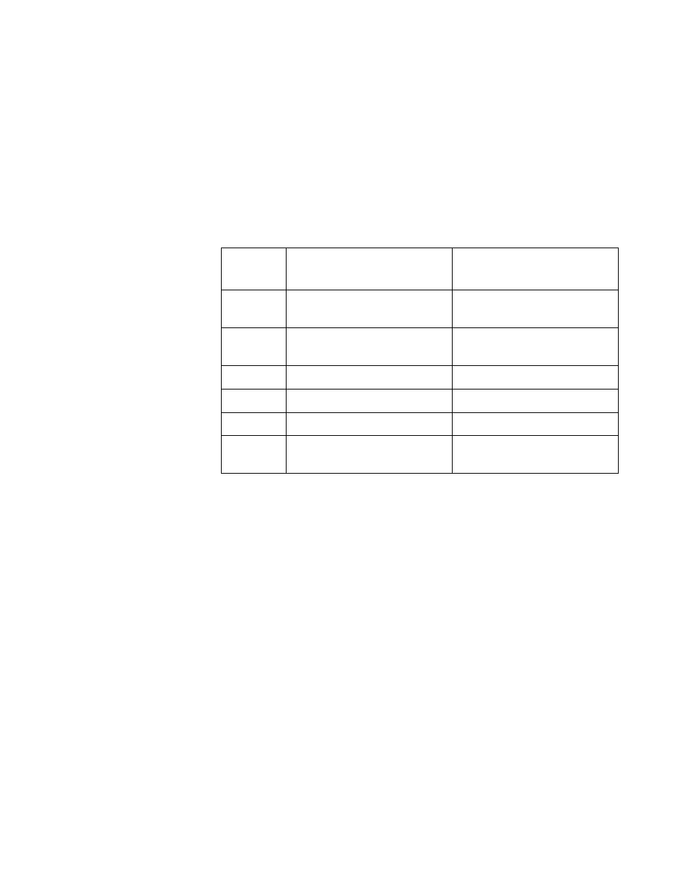
The dimension (X) between the front panel and the rack rails is
given for each rack mounting bracket position in Table 23.
Table 23. Front Panel to Rack Rail Dimensions
Figure #
Front Panel Position
Dimension X
Front Panel to Rack Rail
A
(Factory Installed - Flush)
3.69 mm (0.145 in)
B
(Recessed)
-27.39 mm (-1.078 in)
C
27.39 mm (1.078 in)
D
47.71 mm (1.878 in)
E
140.85 mm (5.545 in)
F
(Reverse Position)
374.16 mm (14.731 in)