Removing the rubber feet, Figure 36: rack mounting hole locations – Allied Telesis AT-SBx31CFC960 User Manual
Page 95
SwitchBlade x3106 Chassis Switch and AT-SBx31CFC960 Card Installation Guide
95
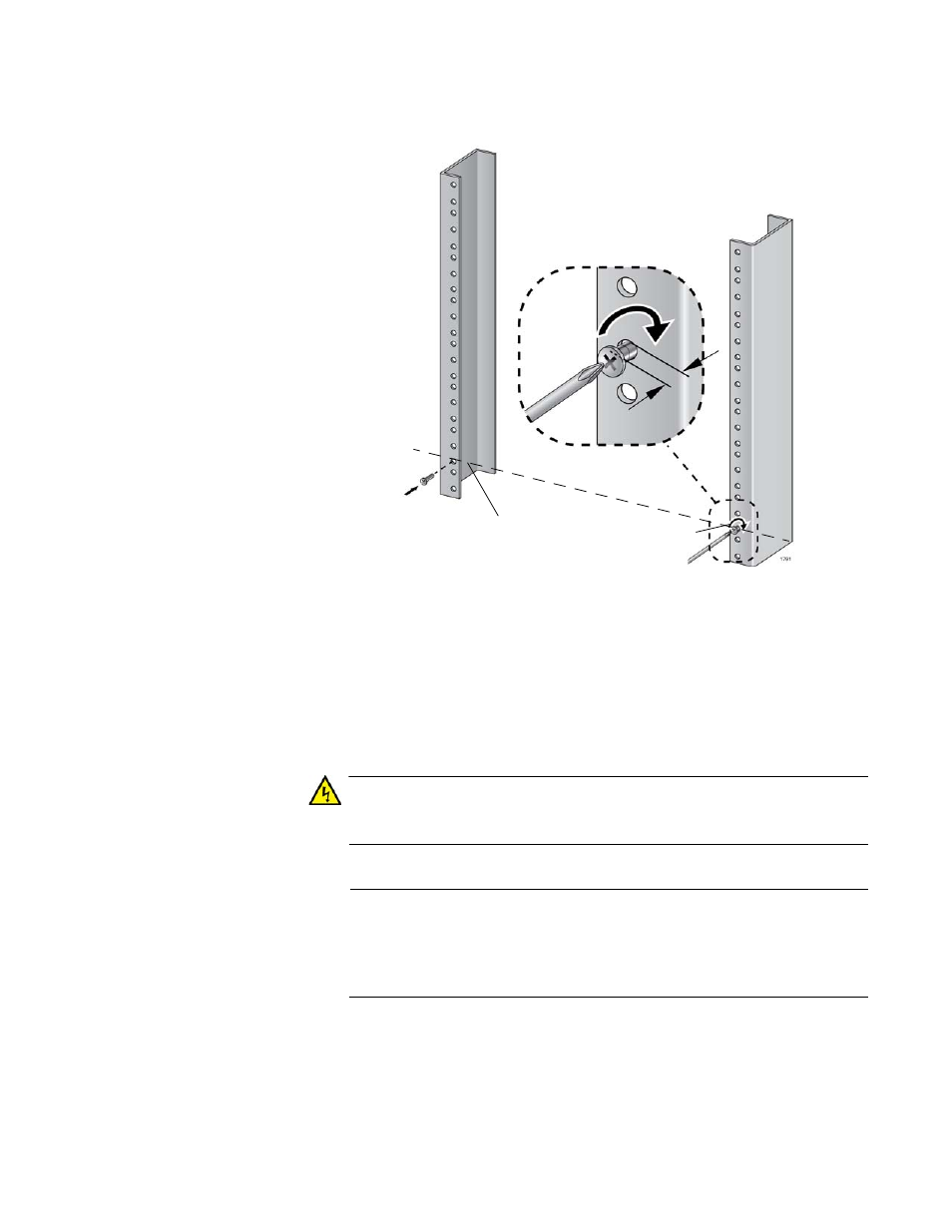
Figure 36. Rack Mounting Hole Locations
5. After installing the two screws in the equipment rack, go to the next
procedure, ”Removing the Rubber Feet”.
Removing the
Rubber Feet
The rubber feet on the bottom of the chassis are for tabletop installation
and should be removed when installing the chassis in an equipment rack.
To remove the rubber feet, perform the following procedure:
Warning
The chassis may be heavy and awkward to lift. Allied Telesis
recommends that you get assistance when lifting the chassis.
Note
Do not remove the shipping brace from the front of the chassis until
after the unit is installed in the equipment rack. You might bend the
chassis and cause misalignment of the slots and card guides if you
lift the chassis without the shipping brace.
1. Place the unit upside down on a level, secure surface, as shown in
6.4 mm (.25 in)
Screw head
Top screw hole of the lowest 1/2” hole pattern
away from rack