Allied Telesis AT-SBx31CFC960 User Manual
Page 49
SwitchBlade x3106 Chassis Switch and AT-SBx31CFC960 Card Installation Guide
49
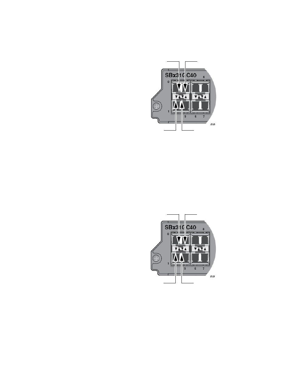
The third and fourth LEDs display the same information for ports 3 and 2,
the right-hand connectors on the bottom and top transceivers,
respectively. See Figure 25.
Figure 25. LEDs for the AT-SBx31GC40 Line Card, with CSFP
Transceivers
When a slot has a standard SFP, only one LED of a pair is active. The
other LED is not used. The active LED is different depending on whether
the slot containing the transceiver is in the top or bottom row. When an
SFP transceiver is installed in a slot in the top row, the first LED is active
and the second inactive. When an SFP transceiver is installed in a slot in
the bottom row, the first LED is inactive and the second active. See
Figure 26.
Figure 26. LEDs for the AT-SBx31GC40 Line Card, with SFP Transceivers
The LED states are described in Table 10 on page 50.
Port 0
L/A LED
Port 2
L/A LED
Port 1
L/A LED
Port 3
L/A LED
Port 0
L/A LED
Not used
Not Used
L/A LED
Port 3