3 selecting, adding, deleting and editing gauges – Innovate Motorsports LogWorks 3 User Manual
Page 42
LogWorks3_Manual_1.01.doc
- 42 -
5.2.2
Vector gauge
A Vector gauge is used to show two channels with the same unit that together form a “vector”. A
vector is a quantity that has both, a magnitude and direction.
The prime example is side-force and acceleration/braking. The combined force is indicated by the
length of the “needle” in the gauge, the direction of the force by the direction of the needle. For
example if acceleration/braking is assigned to the vertical axis and side force to the horizontal
axis, the needle shows the force and direction acting on the tires. The numerical display of the
gauge (upper right corner) shows the value of the combined force.
Min/Max hold does not make direct sense for a vector gauge. Instead the vector gauge records
the max length and direction of the needle with a resolution of 2 degrees and indicates that.
A redline area also does not make sense. Instead for the vector gauge for acceleration and side
force the limits in acceleration, braking, side force left and right are used to create a limit ellipsoid.
The ellipsoid consists of four quarter ellipses for the four quadrants of the gauge. The first one
(from top clockwise) is determined by the acceleration limit and right side force, the second by
right side force holding limit and braking limit, the third by braking limit and left side force holding
limit and the last by left side force limit and acceleration limit.
The total traction force available from the tires described in an ellipsoid on a vector graph is often
called “The Circle of Traction”. If the car is being driven to the traction limit and the needle
touches the ellipsoid, theoretically the car looses traction. The Vector gauge provides an analysis
tool of how efficiently and thoroughly the available traction is being utilized, how close the driver is
getting to the limit of the tires.
5.2.3
Indicator Light
The Indicator light is the simplest gauge. It is usually used to display the state of Bit channels. It
can also be used to create a warning light if a certain value in a value channels is exceeded.
The “Light” color of the indicator is programmable. An Indicator light can be made to simply light
up or to “blink” if on.
5.3 Selecting, adding, deleting and editing gauges.
5.3.1
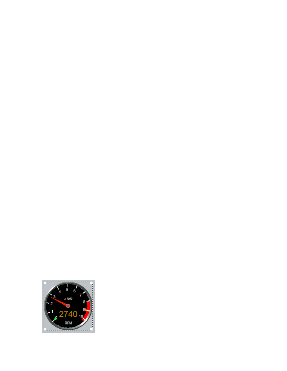
Selecting a gauge
When clicking on a gauge the gauge becomes highlighted as in this: