15 interfacing with various sensors, 1 electronic parts basics, 1 diodes – Innovate Motorsports LogWorks 3 User Manual
Page 138: 2 ic’s, 3 resistors
LogWorks3_Manual_1.01.doc
- 138 -
15 Interfacing with various sensors
15.1 Electronic parts basics
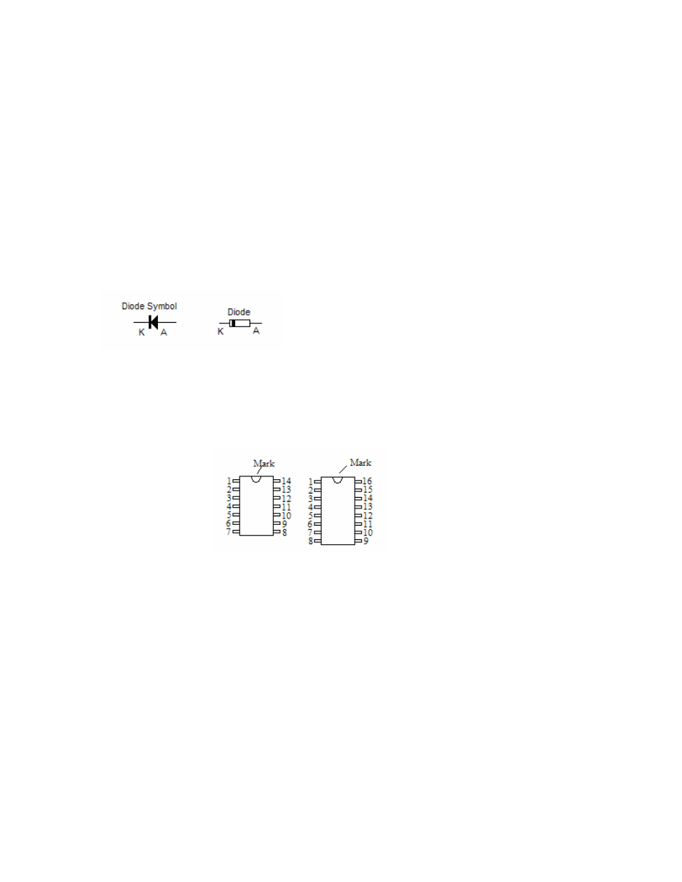
15.1.1 Diodes
Diodes let current pass in one direction (Anode (A) to Cathode (K)) and block current in the other
direction. The exception are Zener diodes. They work like regular diodes, but in the reverse
direction they will pass current only when the voltage is bigger or equal to the ‘Zener’ voltage.
This has the effect of limiting the voltage over the Zener diode to the zener voltage.
On a typical diode the Cathode is marked with a ring as in this picture:
15.1.2 IC’s
Typical IC’s are either surface mount or through-hole. Through-hole ICs are easiest to use. A
typical picture of a 16 pin and 14 pin through-hole IC (DIP) are shown below:
Pin-Number counting starts to the left of the mark and proceeds counter-clock-wise around the
chip.
15.1.3 Resistors
Resistors come in many different values and also different tolerance grades and maximum
wattage. Typical tolerance grades are 10%, 5% and 1% with 5% being the most common.
Wattage ratings are 1W or bigger, 1/2W, 1/4W, 1/8W, and so on. The minimum required wattage
rating can be calculated with:
V
2
/ R
Where V is the max voltage the resistor will see, and R is the resistance in Ohms.
The resistance value and tolerance grade on a typical resistor is marked as colored rings
(typically 4). The first ring being close to one of the connection leads.
The first two rings determine the first two digits of the resistance value. The third ring determines
the number of 0’s to add to the first two digits to get the total value in Ohms.