4 the innovate log-chain concept – Innovate Motorsports LogWorks 3 User Manual
Page 17
LogWorks3_Manual_1.01.doc
- 17 -
2.4 The Innovate Log-Chain concept
LogWorks 3.0 has the capability to log, display and analyze up to 96 engine parameters.
Of those 64 can be regular channels with a variable and programmable range. 32 are reserved
for “Bit Channels”, that can indicate only an on-off condition. Most MTS components read
between 1 and 6 engine parameters. To interface a multitude of MTS components to LogWorks
with a single connection, the Innovate LogChain concept was introduced.
Each of the MTS components has two serial ports (except the LM-1, which has only one). One
serial port is designated as IN-port, the other as OUT port. The OUT-port of one device is
connected to the IN-port of the next device and so on. This way devices can be ‘daisy-chained’ to
build a log-chain for up to 32 channels total. The OUT-port of the last device is connected to the
computer for logging or downloading of logged data.
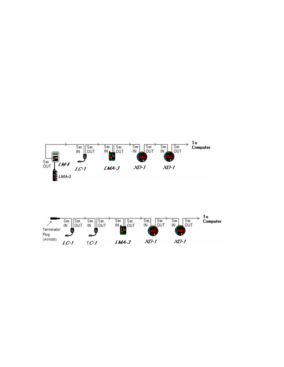
The following diagram shows how to connect multiple MTS devices to form a log-chain. The
example chain consists of a LM-1/LMA-2, a LC-1, a LMA-3 and 2 XD-16’s or XD-1’s. In this case
the chain has 12 channels (6 from LM-1, 1 from LC-1 and 5 from LMA-3).
Devices attached to the LM-1’s analog input count as being part of the LM-1’s 6 channels. They
don’t count extra. XD-1’s do not contribute any channels, so you can add as many as needed.
Another Example Log Chain (7 channels with 2 AFR channels):
The device that’s first in the chain is special. It determines the logging sample rate. The first
device in the chain sends a data packet containing its channel data (a sample) to the next device
(downstream, left to right in the diagram) every 81.92 milliseconds. The next device appends its
data to that packet and hands that packet to the next device downstream and so on. At each
device the packet grows in length. The devices in the chain synchronize their sampling of the
engine parameters to the packets, so that all the channels in a packet together represent the
same instance in time. At the downstream end of the log chain (OUT-port of the last device) a
computer or external logger can be connected to store or display the stream data. The XD-1
display is such a device.
This also means that the complete channel data set is ONLY available at the end of the
log-chain. A datalogger capable of recording the log-chain data-stream therefore MUST be
placed at the end of the log-chain. This includes lap-top computers or other loggers.