2 configuring a thermistor – Innovate Motorsports LogWorks 3 User Manual
Page 36
LogWorks3_Manual_1.01.doc
- 36 -
Schematic case A.
1. Disconnect the sensor from the ECU and measure the voltage between ground
and the sensor pin at the ECU (measurement point MP).
2. Switch the multimeter to current measurement and measure the current in mA
between MP and ground.
Schematic case B.
1. Disconnect the sensor from the ECU and measure the voltage between the two
sensor connection pins of the ECU.
2. Switch the multimeter to current measurement and measure the current in mA
between the two sensor connection pins of the ECU.
The load resistance (in kOhm) is the measured voltage divided by the measured current in mA.
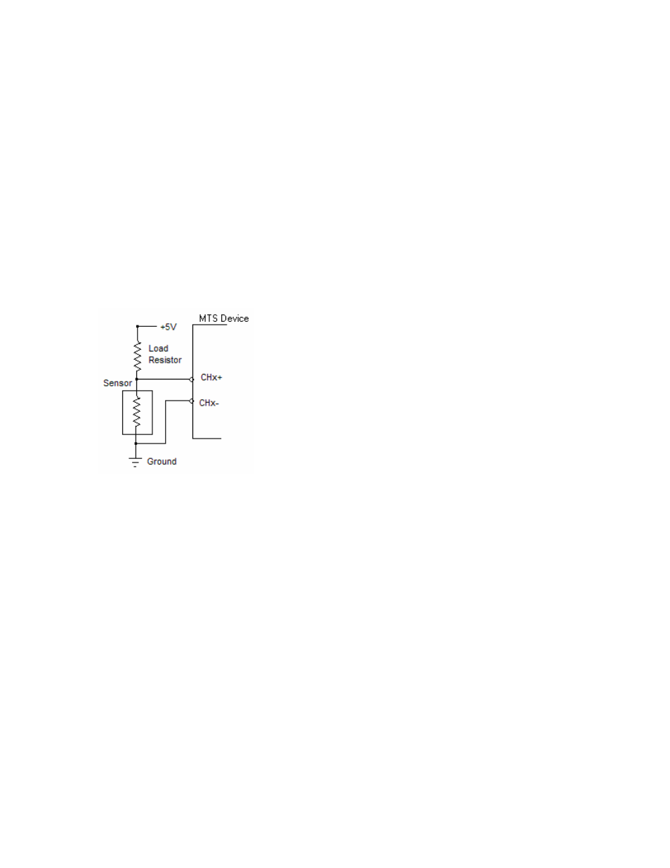
If you use a MTS device with a 0..5V input you have to provide your own load resistor. In case of
the LMA-2 you also have to provide a 5V supply. Connect the load resistor and sensor as follows:
If you are using a MTS device to tap into an existing IAT sensor hooked up to an ECU, omit the
load resistor in the schematic above, but instead rely on the load resistor built into the ECU,
measured as described earlier.
4.2.2
Configuring a Thermistor
The Thermistor calculator creates a thermistor curve by solving the extended thermistor formula:
ln(R) = B1 + B2/T + B3/T
3
Where R is in Ohms and T in Kelvin.