5 measuring duty cycle of peak-hold injectors, 6 making a 5 volt supply for external sensors – Innovate Motorsports LogWorks 3 User Manual
Page 143
LogWorks3_Manual_1.01.doc
- 143 -
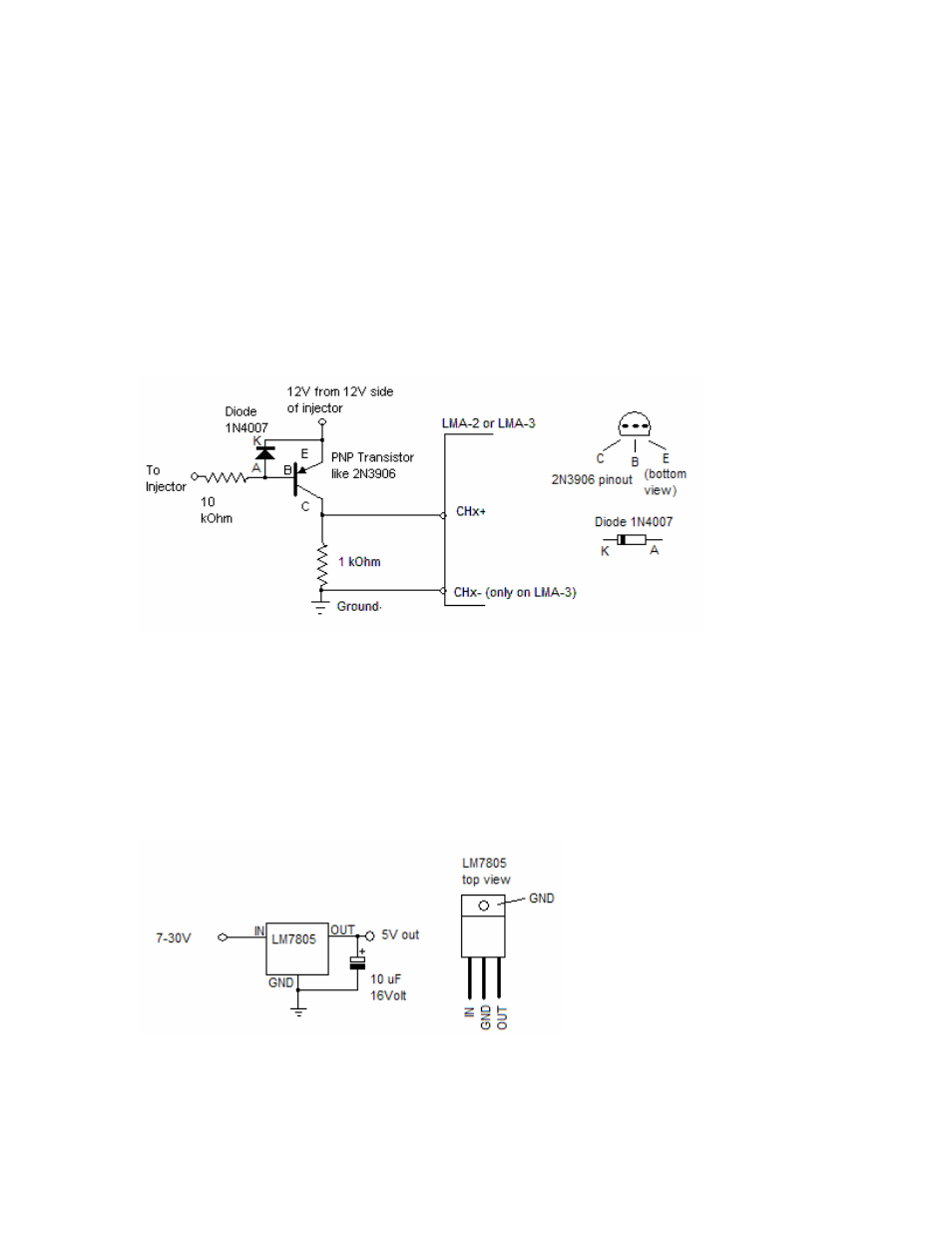
15.5 Measuring duty cycle of peak-hold injectors
Peak-Hold injectors are also called low impedance injectors. The voltage at the active pin of
those injectors during an injection pulse first goes to ground (the peak phase) and then rises to 5
to 10 Volt (the hold phase). Because for the LMA-3/SSI-4/DL-32 everything above 2.5V is high,
the devices can see only the peak phase in many cases, but not the hold phase.
The following circuit allows the devices to be used with regular injectors as well as with peak-hold
injectors.
NOTE:
Some ECU’s control PH injectors in PWM mode. This means that they at first ground the
injector’s active pin during the peak phase, and then rapidly switch ground on-and off
during the hold phase. This circuit will NOT work for that method of control.
When setting up the duty cycle measurement in LogWorks, positive duty cycle must be used
compared to negative duty cycle as when the LMA-3 is directly connected to an injector.
15.6 Making a 5 Volt supply for external sensors
This simple circuit will create a stable 5V supply from a 7-30 Volt source. Max current should be
about 300mA without heat sink on the regulator. 800-900mA with heat-sink.
A LM340 can be used instead of an LM7805 as well. The 10uF capacitor is optional (reduces
noise).