HP Integrity rx4610 Server User Manual
Page 51
Chapter 5
Installing Additional Memory
43
3
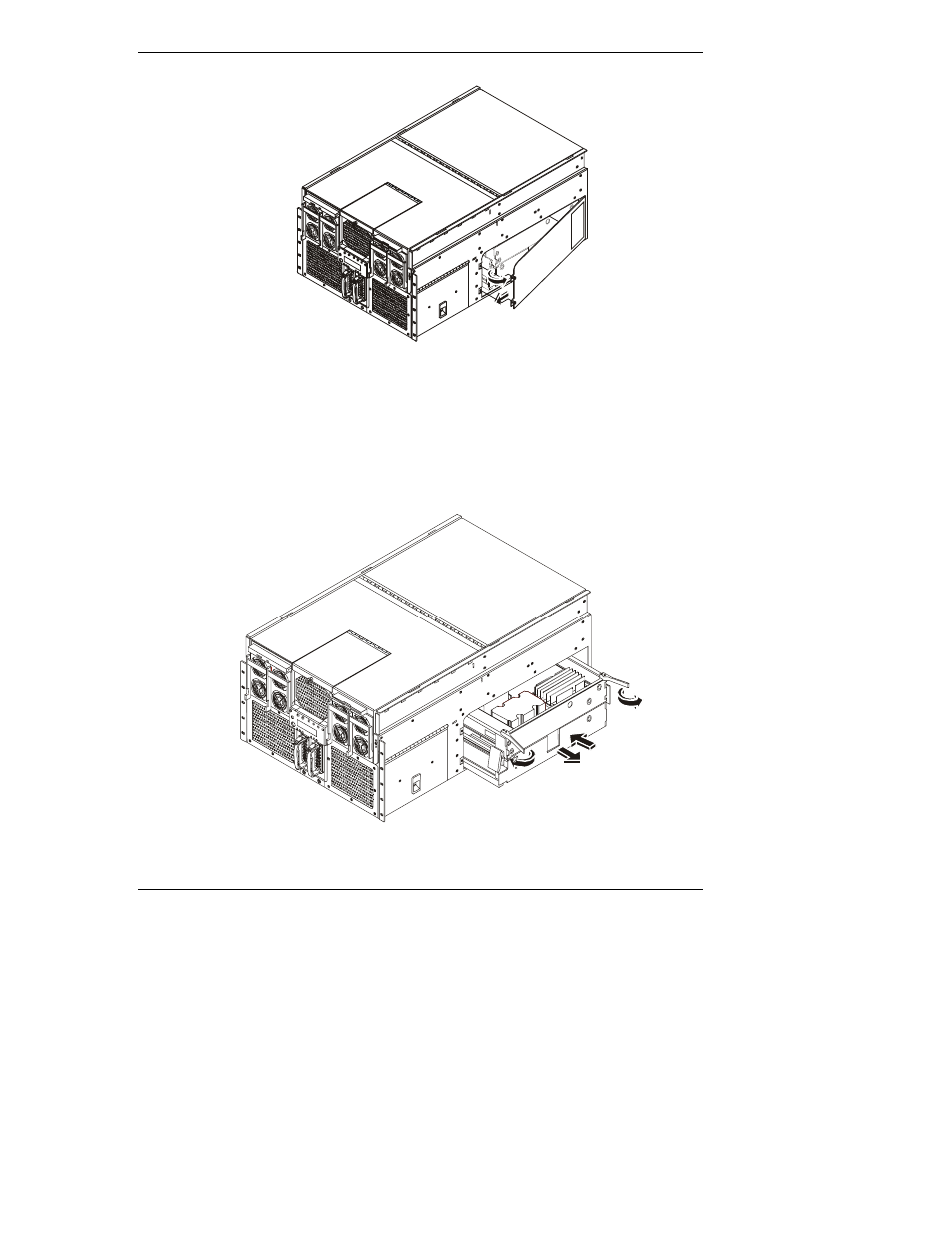
Figure 5-1. Opening the Processor/Memory Complex Bay Cover
7. Remove the four screws that secure the complex to the chassis. These
screws are located on the left side of the chassis as you face the front of the
system.
8. Rotate the two extraction levers on the sides of the module to eject it from
the Sideplane board connector.
Figure 5-2. Removing the Processor/Memory Complex
See also other documents in the category HP Computer hardware:
- xt1500 (58 pages)
- LaserJet 4700 (68 pages)
- ProLiant DL388p Gen8 Server (128 pages)
- ProLiant BL460c Gen8 Server Blade (67 pages)
- ProLiant DL360 Server (16 pages)
- ProLiant BL460c Gen8 Server Blade (65 pages)
- ProLiant BL465c Server Blade (87 pages)
- ProLiant DL388p Gen8 Server (47 pages)
- ProLiant BL40p Server series (73 pages)
- ProLiant ML115 Server (63 pages)
- ProLiant DL140 G2 Server (81 pages)
- Servidor HP ProLiant ML370 G4 (20 pages)
- Servidor HP ProLiant ML370 G4 (30 pages)
- Servidor HP ProLiant DL160 G5p (84 pages)
- Servidor HP ProLiant DL980 G7 (143 pages)
- Servidor HP ProLiant DL380 G5 (137 pages)
- Integrity rx2620 Servers (55 pages)
- 9000 rp3440 Servers (36 pages)
- Integrity rx2620 Servers (42 pages)
- Integrity rx2620 Servers (48 pages)
- Integrity rx2620 Servers (53 pages)
- Integrity rx2620 Servers (24 pages)
- Integrity rx2620 Servers (33 pages)
- Integrity rx2620 Servers (100 pages)
- Integrity rx2620 Servers (37 pages)
- Integrity Superdome sx1000 Server (53 pages)
- Integrity rx2620 Servers (37 pages)
- Integrity rx2620 Servers (58 pages)
- Integrity rx2620 Servers (77 pages)
- Integrity rx2620 Servers (107 pages)
- Servidor HP ProLiant DL360p Gen8 (129 pages)
- Servidor HP ProLiant DL120 G6 (133 pages)
- ProLiant MicroServer Gen8 (95 pages)
- ProLiant DL580 Gen8 Server (91 pages)
- ProLiant MicroServer (94 pages)
- ProLiant BL685c G5 Server Blade (99 pages)
- ProLiant Firmware Maintenance CD (87 pages)
- ProLiant BL40p Server series (30 pages)
- ProLiant BL10e Server Blade (232 pages)
- Serveur lame HP ProLiant BL680c G5 (90 pages)
- Serveur lame HP ProLiant BL465c Gen8 (578 pages)
- ProLiant DL320e Gen8 Server (96 pages)
- ProLiant ML110 G7 Server (113 pages)
- Integrity Superdome sx1000 Server (19 pages)
- 9000 rp8420 Servers (38 pages)