Dlp-700 – ADC Release 3.1 User Manual
Page 65
1152700
•
Issue 1
•
February 2001
•
Section 2 Operations and Maintenance
Page 2-45
© 2000, ADC Telecommunications, Inc.
DLP-700
Page 1 of 1
POWER UP A CELLWORX STN NODE
Summary: This procedure provides instructions for verifying the source
−
48 Vdc power supply.
1. Turn on the power source that will supply power to the system.
2. Use a multi-tester to measure the DC voltage at the source. When testing, place the positive
probe on the
−
48 V terminal and the negative probe on the COM or RTN terminal.
3. The measured voltage must be between
−
42.5 Vdc and
−
56.5 Vdc at the specified point.
Was voltage within range specified? Note the polarity.
If No, proceed to step 4.
If Yes, continue with step 5.
4. The problem is in the power supply wiring or in the
−
48 Vdc power supply. Isolate the
problem using local troubleshooting practices and correct as required before installing
power to the system. Repeat procedure after correcting problem.
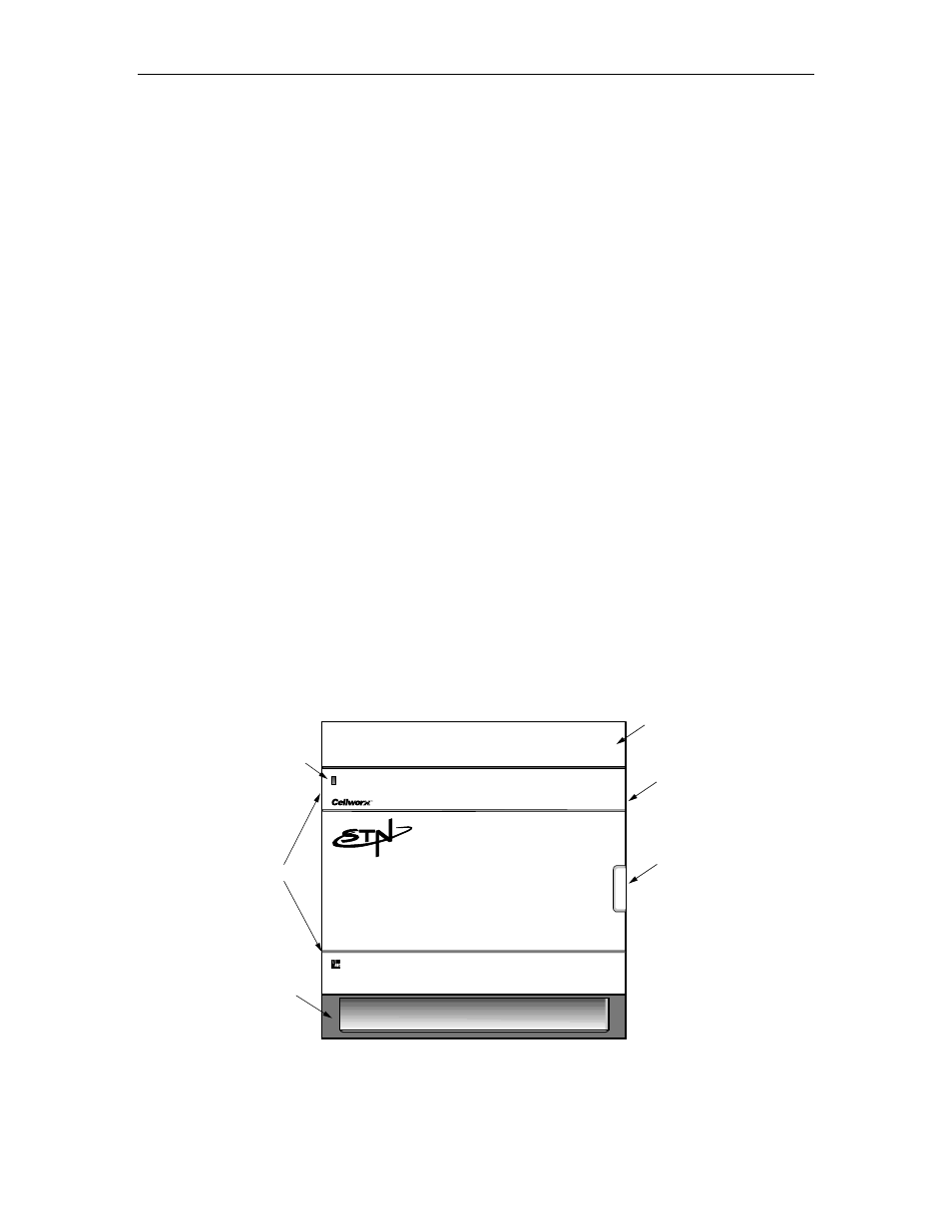
5. Install fuses or engage the circuit breakers that supply power to the shelf. The front access
cards should illuminate. This can be verified by observing the shelf alarm indicator on the
front door panel. This will only light up if the SC cards are installed and an alarm is
present. Refer to Figure 700-1.
Stop! You have completed this procedure.
DOOR
HINGES
DOOR
LATCH
SHELF
ALARM
INDICATOR
UPPER HEAT BAFFLE/
FIBER MANAGEMENT TRAY
LOWER AIR INTAKE/
CABLE ROUTING TRAY
ESD GROUND JACK
10479-C
Figure 700-1. Cellworx STN Component Identification