Dlp-781 – ADC Release 3.1 User Manual
Page 357
1152700
•
Issue 1
•
February 2001
•
Operation and Maintenance
Page 2-337
© 2000, ADC Telecommunications, Inc.
DLP-781
Page 1 of 3
REMOVING A NMIC CARD FROM THE SHELF
Summary: If replacing a defective NMIC card, it is preferable that it be shut down before
removing.
1. If the NMIC is responsive to commands, plug the computer cable into the front access port
located under the hinged front panel. Otherwise, go to step 4.
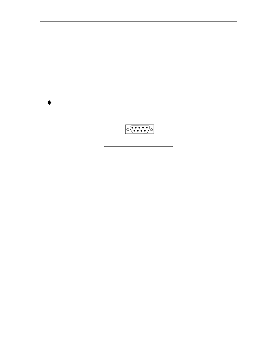
Note: A terminal emulator (ProComm Plus or HyperTerminal) needs to be set up using
9600bps, 8bits, 1stop bit and no parity using a DB9 null modem cable wired as shown in
Figure 781-1.
1
2
3
4
5
6
7
8
9
PIN # FUNCTION STANDARD USAGE
2
3
5
OUTPUT
INPUT
REFERENCE
TRANSMIT DATA
RECEIVE DATA
LOGIC GROUND
10564-B
Figure 781-1. NMIC RS232 Port Cable Connector Wiring
2. At the Login: prompt. Log into the NMIC. From the factory the userid is root with NO
password set. If the NMIC has been set up previously and you do not know the name and
password, see your system administrator.
3. After logging into the NMIC a bash# prompt will appear Enter the following commands to
execute a NMIC shut down:
•
/usr/bin/killall psm
- Stops processes running on NMIC. If NMIC is
fully operational than use this command. An operational NMIC can be
identified by the two green LEDs, Status and Active.
•
/usr/bin/shutdown –h
- Shuts down NMIC and halts it.
4. To remove a card from the shelf, pry outward on the ejector ears using the thumbs. This
will dislodge the card from the backplane and allow it to be withdrawn from the card
guides. Refer to Figure 781-2 for an example of removing a card from the front of the shelf.
5. Using one hand to support the card underneath as it is drawn out, remove the card with the
other hand.
6. Place the card in an Electro-statically protected bag and place in the proper packaging
material in anticipation for its return to ADC Telecommunications for evaluation.
7. Align the replacement card with the card guides in the shelf at the proper slot position
holding the card with the component side facing right. Refer to Figure 781-3.