NORD Drivesystems BU0700 User Manual
Page 92
NORDAC SK 700E Operating Manual
92
Subject to technical alterations
BU 0700 GB-1411
Parameter
Setting value / Description / Note
Available with option
P523
Factory setting
always visible
0 ... 2
[ 0 ]
By selecting the appropriate value and confirming it with the ENTER key, the selected parameter range
is entered in the factory setting. Once this setting is made, the parameter value automatically changes
back to 0.
0 = No change: Does not change the parameterisation.
1 = Load factory setting: The complete parameterisation of the FI reverts to the factory setting. All
originally parameterised data are lost.
2 = Factory settings without bus: All parameters of the frequency inverter, with the exception of the
Bus parameter, are reset to the factory setting.
P533
Factor I
2
t-Motor
Always visible
50 ... 150 %
[ 100 ]
from SW3.4 and
above
The motor current for the I
2
t motor monitoring P535 can be weighted with the parameter P533. Larger
factors permit larger currents.
P535
I
2
t motor
always visible
0 ... 1
[ 0 ]
When calculating the motor temperature, the output current, time and the output frequency (cooling)
are taken into account. If the temperature limit value is reached then switch off occurs and error
message E002 (motor overheating) is output. Possible positive or negative acting ambient conditions
cannot be taken into account here.
0 = Switched off
1 = Switched on
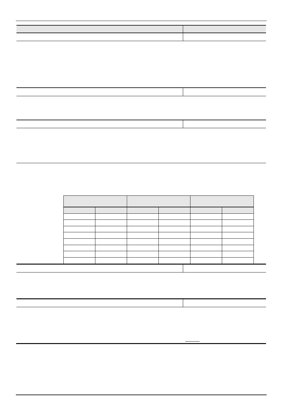
0 … 24
[ 0 ]
from SW3.4 and
above
The I
2
t motor function can now be set in a differentiated manner. Up to four curves with three different
triggering times can be set. The trigger times are based on classes 5, 10 and 20 for semiconductor
switching devices.
Setting 5 corresponds to the previous setting “ON”. All curves run from 0Hz to
half of the nominal frequency (P201). From half of the nominal frequency upwards, the full nominal
current is available.
Switch-off class 5,
60s at 1.5x I
N
Switch-off class 10,
120s at 1.5x I
N
Switch-off class 20,
240s at 1.5x I
N
I
N
at 0Hz
P535
I
N
at 0Hz
P535
I
N
at 0Hz
P535
100%
1
100%
9
100%
17
90%
2
90%
10
90%
18
80%
3
80%
11
80%
19
70%
4
70%
12
70%
20
60%
5
60%
13
60%
21
50%
6
50%
14
50%
22
40%
7
40%
15
40%
23
30%
8
30%
16
30%
24
P536
Current limit
always visible
0.1...2.0 / 2.1
(x the FI nominal
current)
[ 1.5 ]
The inverter output current is limited to the set value. (as before "Increase delay") If this limit value is
reached, the inverter reduces the actual output frequency.
0,1 - 2,0 = Multiplier with the inverter nominal current gives the limit value
2,1 = OFF represents the switching off of this limit value.
P537
Pulse disconnection
always visible
0 ... 1
[ 1 ]
This function prevents immediate switch-off of the inverter if there is a heavy overload (>200% inverter
current). With the current limit switched on the output current is limited to approximately 150% of the
inverter nominal current. This limit is brought about by a brief switch-off of the end stage.
0 = Switched off
1 = Switched on
Note: For equipment from 30kW the function Pulse switch-off cannot be switched off.