NORD Drivesystems BU0700 User Manual
Page 128
NORDAC SK 700E Operating Manual
128
Subject to technical alterations
BU 0700 GB-1411
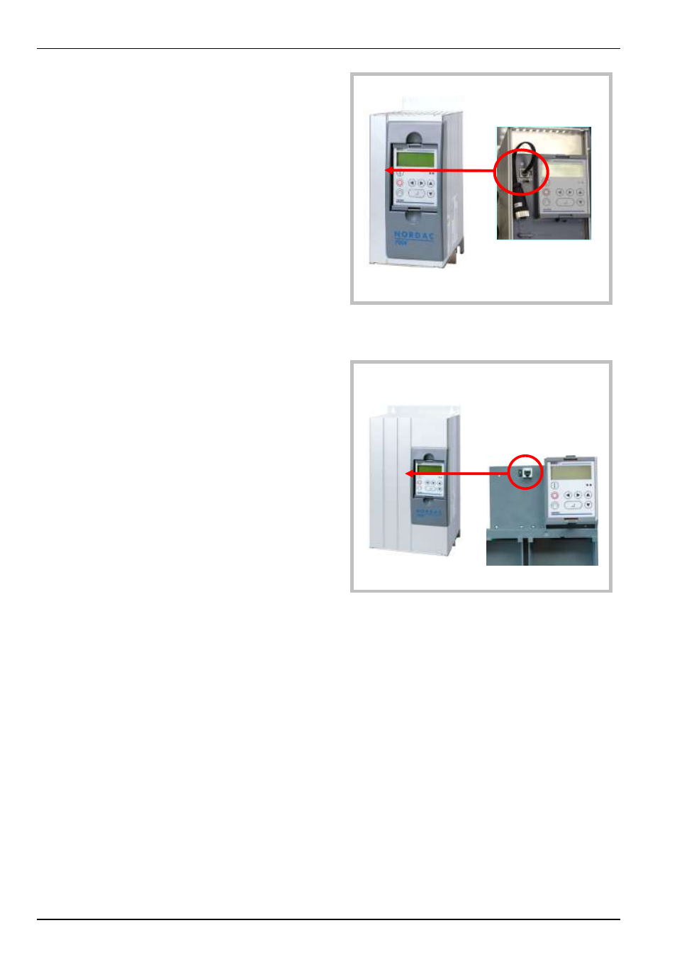
8.8.1 SK 700E up to 22kW
This connection option can be optionally ordered for devices from
1.5 to 22kW. The type designation of the devices is then
SK 700E-xxx-340-A-RS2.
The socket is located under the blank screw caps in the cover of
the device, on the left next to the technology unit slot.
A 120 Ω termination resistor can be connected via the DIP switch
located next to the RJ12 socket. The DIP switch must be set to the
"ON" position if the frequency inverter communicates as the first or
last participant via RS 485.
8.8.2 SK 700E from 30kW
This connection is available in the standard designs for devices
from 30 to 160kW.
The socket is located under the device cover, left next to the
technology unit slot.
A 120 Ω termination resistor can be connected via the DIP switch
located next to the RJ12 socket. The DIP switch must be set to the
"ON" position if the frequency inverter communicates as the first or
last participant via RS 485.
RJ12
“on board“ BG 1-4 (option)
RJ12 ”on board“ BG 5-8 (standard)