3 motor data / characteristic curve parameters – NORD Drivesystems BU0700 User Manual
Page 69
5.1.3 Motor data
BU 0700 GB-1411
Subject to technical alterations
69
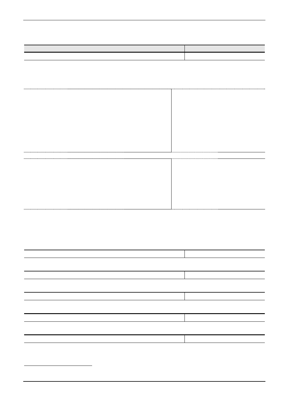
5.1.3 Motor data / characteristic curve parameters
Parameter
Setting value / Description / Note
Available with option
P200 (P)
Motor list
always visible
0 ... 32 / 27
[ 0 ]
With this parameter, the motor data presets can be changed. The default setting is a 4 pole DC
standard motor with the nominal FI power.
Select one of the possible digits and press the ENTER key to set all of the following motor parameters
(P201 to P209). The motor data is based on 4-pole DC standard motors.
Only relevant power outputs for the corresponding FI outputs are shown.
NOTE:
Settings for devices
1.5...22kW
0 = No change to data
1 = No motor *
2 = 0,25 kW
3 = 0,37 kW
4 = 0,55 kW
5 = 0,75 kW
6 = 1,1 kW
7 = 1,5 kW
8 = 2,2 kW
9 =
3,0 kW
10 = 4,0 kW
11 = 5,5 KW
12 = 7,5 kW
13 = 11 kW
14 = 15 kW
15 = 18,5 kW
16 = 22 kW
17 = 30 kW
18 = 0,25 PS
19 = 0,5 PS
20 = 0,75 PS
21 = 1,0 PS
22 = 1,5 PS
23 = 2,0 PS
24 = 3,0 PS
25 = 5,0 PS
26 = 7 PS
27 = 10 PS
28 = 15 PS
29 = 20 PS
30 = 25 PS
31 = 30 PS
32 = 40 PS
NOTE:
Settings for devices
30...160kW
0 = No change to data
1 = No motor *
2 = 11 kW
3 = 15 kW
4 = 18,5 kW
5 = 22 kW
6 = 30 kW
7 = 37 kW
8 =
45 kW
9 =
55 kW
10 = 75 kW
11 = 90 kW
12 = 110 kW
13 = 132 kW
14 = 160 kW
15 = 15 PS
16 = 20 PS
17 = 25 PS
18 = 30 PS
19 = 40 PS
20 = 50 PS
21 = 60 PS
22 = 75 PS
23 = 100 PS
24 = 120 PS
25 = 150 PS
26 = 180 PS
27 = 220 PS
Note:
Control of the motor set is possible via parameter P205 (P200 is reset to 0 after input
confirmation).
*) With an input value of 1 (= no motor), a mains simulation can be parameterised. This requires the
following data to be set: 50.0Hz / 1500 rpm / 15.00A / 400V / cos
=0.90 / Stator resistance 0.01
In
this setting, the inverter operates without current control, slip compensation and pre-magnetising time,
and is therefore not recommended for motor applications. Possible applications are induction furnaces
or other applications with coils and transformers.
P201 (P)
Nominal frequency
always visible
20.0...399.9
[
]
The motor nominal frequency determines the V/f break point at which the FI supplies the nominal
voltage (P204) at the output.
P202 (P)
Nominal speed
always visible
300...24000 rpm
[
]
The nominal motor speed is important for the correct calculation and control of the motor slip and the
speed display (P001 = 1).
P203 (P)
Nominal current
always visible
0.1...540.0 A
[
]
The nominal motor current is a decisive parameter for the current vector control.
P204 (P)
Nominal voltage
always visible
100...800 V
[
]
The >Nominal voltage< matches the mains voltage to the motor voltage. In combination with the
nominal frequency, the voltage/frequency characteristic curve is produced.
P205 (P)
Nominal power
always visible
0.00... 315 kW
[
]
The motor nominal power controls the motor set via P200.
These setting values are dependent on the selection in parameter P200.