1 basic i/o – NORD Drivesystems BU0700 User Manual
Page 45
3.2 Customer unit
BU 0700 GB-1411
Subject to technical alterations
45
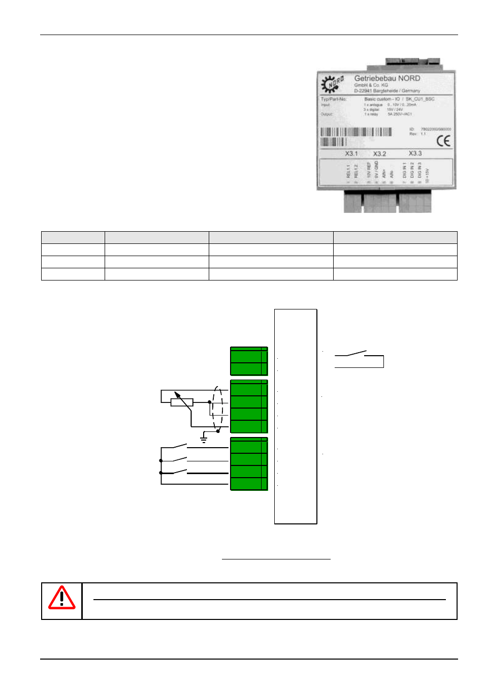
3.2.1 Basic I/O
(SK CU1-BSC, Option)
The Customer Unit Basic I/O provides sufficient control terminals for simple control
tasks and is therefore an economic solution for many applications.
1 analog input and 3 digital outputs are available to control the frequency inverter.
The analog differential input can process positive signals of 0...10V.
By means of a relay contact, brake control and even warnings to another system
can be initiated. There are a total of 13 different relay functions available.
The digital inputs of the Basic I/O can also be assigned analog functions (see
process controller, Chapter 8.2).
Here, input voltages ≥10V are processed as 10V
signals and correspond to 100%.
(9V = 90%, ... , 0V=0%)
Connector
Functions
Maximum cross-section
Parameter
X3.1
Output relay
1.5 mm
2
P434 ... P436
X3.2
Analog input
1.5 mm
2
P400 ... P408
X3.3
Digital inputs
1.5 mm
2
P420 ... P422
NOTE: All control voltages are based on a common reference potential!
Potentials AGND /0V und GND /0V are internally linked in the device.
The maximum total current 5/15V is 300mA!
Floating contacts or
output of a PLC: 7,5...33V
(low = 0...3,5Volt)
Differential input
0...10 V
X
3
.1
X
3
.2
X
3
.3
01 REL1.1
02 REL1.2
11 VREF 10V
12 AGND /0V
13 AIN1 -
14 AIN1 +
21 DIG IN 1
22 DIG IN 2
23 DIG IN 3
42 VO +15V
Digital inputs:
DIG IN 1 = On right
DIG IN 2 = On left
DIG IN 3 = Parameter set bit 0
Output relay:
max. 2,0A
28V DC /230 V AC
U
REF
= 10 V / I
max
= 10 mA
0V, gnd
Power supply: 15V
PLC analog output: 0...10V
or potentiometer: 2...10k
WARNING / NOTE
It is not permissible to connect the output relay of the Customer Unit (SK CU...and SK XU) to dangerous
voltages(≥60VAC) if a contact of the relay is connected to a circuit with safe isolation.