P102 ps1, Acceleration time 2,90 s, P1001 – NORD Drivesystems BU0700 User Manual
Page 28: P1002, P1003, P1004
NORDAC SK 700E Operating Manual
28
Subject to technical alterations
BU 0700 GB-1411
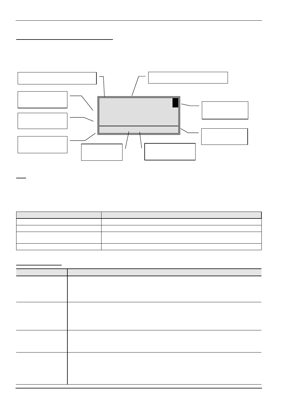
Screen layout during parameterisation
If the setting of a parameter is changed, then the value flashes intermittently until confirmed with the ENTER key. In order to
retain the factory settings for the parameter being edited, both VALUE keys must be operated simultaneously. Even in this case,
the setting must be confirmed with the ENTER key for the change to be stored.
If the change is not to be stored, then pressing one of the SELECTION keys will cal up the previously stored value. Further
operation of a VALUE key leaves this parameter.
P102
PS1
3
Acceleration time
2,90 s
ONLINE
FI P1
E BLOCK
Note:
The lowest line in the display is used to display the current status of the box and the frequency inverter being
controlled.
3.1.1.1 ParameterBox parameters
The following main functions are assigned to the menu groups:
Menu group
No.
Master function
Display
(P10xx):
Selection of operating values and display layout
Parameterisation
(P11xx):
Programming of the connected inverter and all storage media
Parameter management
(P12xx):
Copying and storage of complete parameter sets from storage media and
inverters
Options
(P14xx):
Setting the functions of the ParameterBox, as well as all automatic processes
Parameter display
Parameter
Setting value / Description / Note
P1001
Bus scan
A bus scan is initiated with this parameter. During this process a progress indicator is shown in the
display.
After a bus scan, the parameter is "Off".
Depending on the result of this process, the ParameterBox goes into the "ONLINE" or "OFFLINE"
operating status.
P1002
Inverter select
Selection of the current item to be parameterised/controlled.
The display and further operating actions refer to the item selected. In the inverter selection list,
only those devices detected during the bus scan are shown. The actual object appears in the status
line.
Value range: FI, S1 ... S5
P1003
Display mode
Selection of the operating values display for the ParameterBox
Standard
Any 3 values next to each other
List
Any 3 values with units below each other
Large display
1 value (any) with unit
P1004
Values to display
Selection of a display value for the actual value display of the ParameterBox.
The value selected is placed in the first position of an internal list for the display value and is then
also used in the Large Display mode.
Possible actual values for the display: Speed of rotation Link voltage
Setpoint frequency
Torque current
Speed of rotation Current
Voltage
Actual frequency
Parameter set to be edited
Parameter to be edited (No.)
Parameter to be
edited (text)
Current parameter
value
Actual status of the
ParameterBox
Selected
control medium
Status of the
control medium
Menu
structure level
Active parameter set
in control medium