5 colour and contact assignments for the encoder – NORD Drivesystems BU0700 User Manual
Page 57
3.4 Klemmebelegung
BU 0700 GB-1411
Subject to technical alterations
57
Function
Data
Desig-
nation
Customer Units / Special Extension Units
Terminal
Serial interface
Electrically isolated input
Transfer rate USS up to
38400 Baud
Transfer rate CAN up to 500
kBaud
Transfer rate Profibus up to
1.5 Mbaud
Profibus 24V
12 MBaud
BSC
STD
MLT
USS
CAN
PBR
POS
ENC
RS485 +
-
X1.4.73
-
X4.3.73
-
-
-
-
RS485 -
-
X1.4.74
-
X4.3.74
-
-
-
-
CAN1 H
-
-
-
-
X5.3.75
-
-
-
CAN1 L
-
-
-
X5.3.76
-
-
-
PBR A
-
-
-
-
-
X6.3.81
-
-
PBR B
-
-
-
-
-
X6.3.82
-
-
PBR RTS
-
-
-
-
-
X6.3.83
-
-
PBR A
-
-
-
-
-
X6.4.81
-
-
PBR B
-
-
-
-
-
X6.4.82
-
-
SHIELD
-
-
-
-
-
X6.4.90
-
-
Incremental encoder
TTL, RS 422
max. 250kHz
500
– 8192 pulse/revolution
BSC
STD
MLT
USS
CAN
PBR
POS
ENC
ENC1 A+
-
-
-
-
-
-
X10.4.51 X11.2.51
ENC1 A-
-
-
-
-
-
-
X10.4.52 X11.2.52
ENC1 B+
-
-
-
-
-
-
X10.4.53 X11.2.53
ENC1 B-
-
-
-
-
-
-
X10.4.54 X11.2.54
ENC1 N+
-
-
-
-
-
-
X10.4.55
-
ENC1 N-
-
-
-
-
-
-
X10.4.56
-
Absolute encoder
SSI, RS 422
24 bit
BSC
STD
MLT
USS
CAN
PBR
POS
ENC
SSI1 CLK+
-
-
-
-
-
-
X10.3.63
-
SSI1 CLK-
-
-
-
-
-
-
X10.3.64
-
SSI1 DAT+
-
-
-
-
-
-
X10.3.65
-
SSI1 DAT-
-
-
-
-
-
-
X10.3.66
-
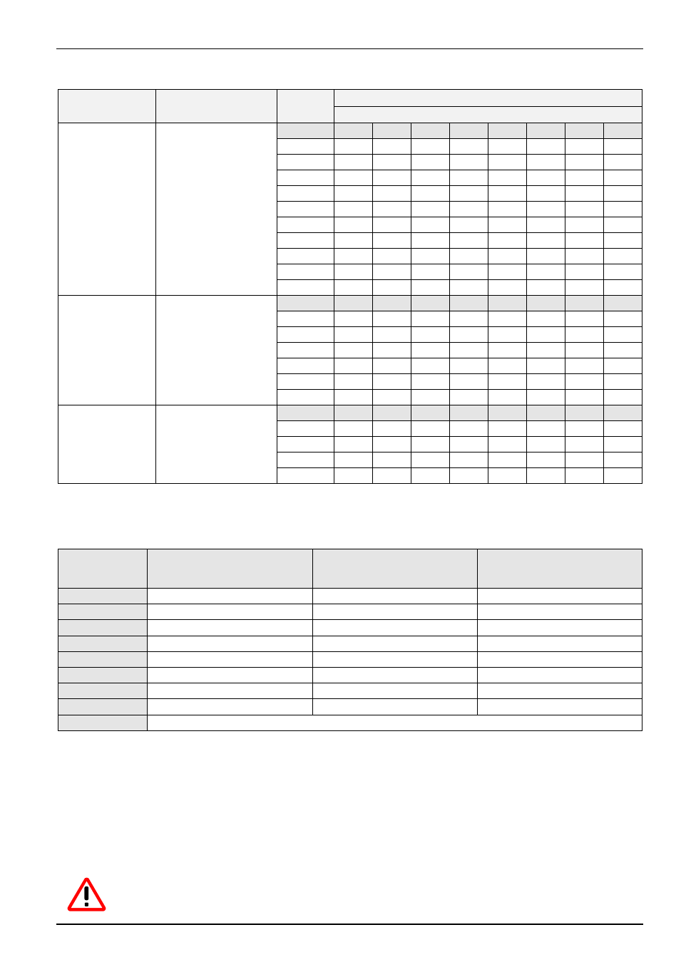
3.5 Colour and contact assignments for the encoder
Function
Cable colours for incremental
encoder {xe "Incremental
encoder"}
Assignment for encoder option,
SK XU1-ENC
Assignment for PosiCon option,
SK XU1-POS
15V supply
brown / green
X11.1.42 VO +15V
X10.2.42 VO +15V
0V GND
white / green
X11.1.40 GND /0V
X10.4.40 GND /0V
Track A
brown
X11.2.51 ENC1 A+
X10.4.51 ENC1 A+
Track A inverse
green
X11.2.52 ENC1 A-
X10.4.52 ENC1 A-
Track B
grey
X11.2.53 ENC1 B+
X10.4.53 ENC1 B+
Track B inverse
pink
X11.2.54 ENC1 B-
X10.4.54 ENC1 B-
Track 0
red
--
X10.4.55 ENC1 N+
Track 0 inverse
black
--
X10.4.56 ENC1 N-
Cable shield
connected to a large area of the frequency inverter housing or shielding angle
NOTE:
If there are deviations from the standard equipment (Type 5820.0H40, 10-30V encoder, TTL/RS422)
for the motors, please note the accompanying data sheet or consult your supplier.
RECOMMENDATION: For greater operating safety, in particular with long connection cables, we recommend the use of a
higher power supply (15V/24V) and an incremental encoder for 10-30V power supply. The signal level
must remain at 5V TTL.
ATTENTION:
The rotation field of the incremental encoder must correspond to that of the motor. Therefore,
depending on the rotation direction of the encoder to the motor (possibly reversed), a negative sign
number must be set in parameter P301.