NORD Drivesystems BU0700 User Manual
Page 78
NORDAC SK 700E Operating Manual
78
Subject to technical alterations
BU 0700 GB-1411
Parameter
Setting value / Description / Note
Available with option
P403
Adjustment 1 100%
BSC STD MLT
-50.0 ... 50.0 V
[ 10.0 ]
This parameter is used to set the voltage corresponding to the maximum value of the selected function
for analog input 1.
In the factory setting (setpoint) this value is corresponds with the setpoint set via P105 >Maximum
frequency<.
Typical setpoints and corresponding settings:
0
– 10 V
10.0 V
2
– 10 V
10.0 V (for function 0-10 V monitored)
0
– 20 mA
5.0 V (internal resistance approx. 250
)
4
– 20 mA
5.0 V (internal resistance approx. 250
)
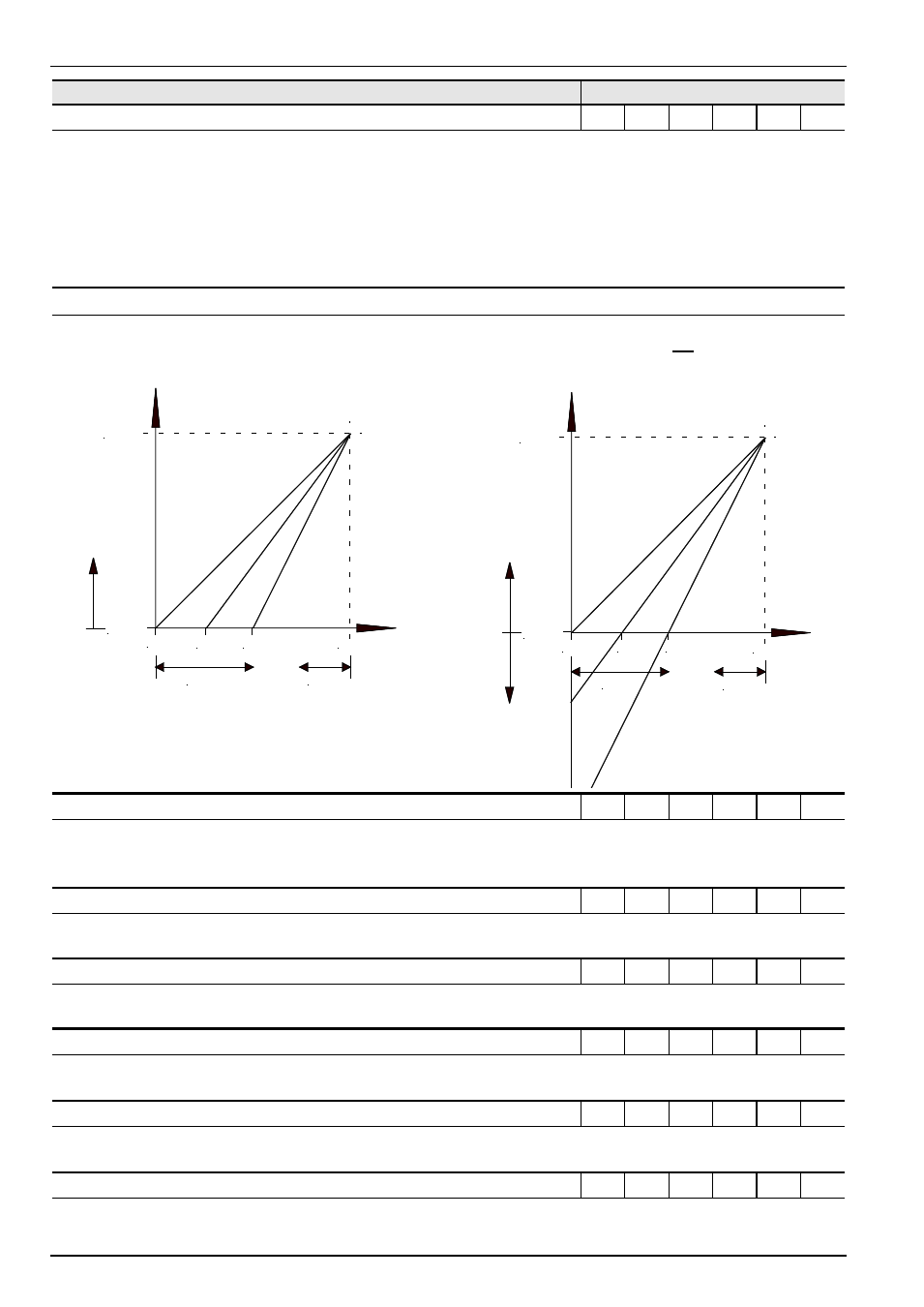
P400 ... P403
P401 = 0 0
–10V limited
0.0V
2.5V
5.0V
10.0V
P105
P104
P402
P403
output
frequency
setpoint
voltage
positive
P401 = 1 0
–10V not limited
0.0V
2.5V
5.0V
10.0V
P105
P104
P402
P403
output
frequency
setpoint
voltage
positive
negative
P404
Filter analog input 1
BSC STD MLT
10 ... 400 ms
[ 100 ]
Adjustable digital low-pass filter for the analog signal.
Interference peaks are hidden, the reaction time is extended.
P405
Analog 2 input function
MLT
0...18
[ 0 ]
This parameter is identical to P400, but refers to P406, P407, P408, P409.
P406
Mode analog input 2
MLT
0...3
[ 0 ]
This parameter is identical to P401, but refers to P405, P407, P408, P409.
P407
Adjustment 2 0%
MLT
-50.0 ... 50.0 V
[ 0.0 ]
This parameter is identical to P402, but refers to P405, P406, P408, P409.
P408
Adjustment 2 100%
MLT
-50.0 ... 50.0 V
[ 10.0 ]
This parameter is identical to P403, but refers to P405, P406, P407, P409.
P409
Filter analog input 2
MLT
10 ... 400 ms
[ 100 ]
This parameter is identical to P404, but refers to P405, P406, P407, P408.