NORD Drivesystems BU0700 User Manual
Page 51
3.3 Special extension unit
BU 0700 GB-1411
Subject to technical alterations
51
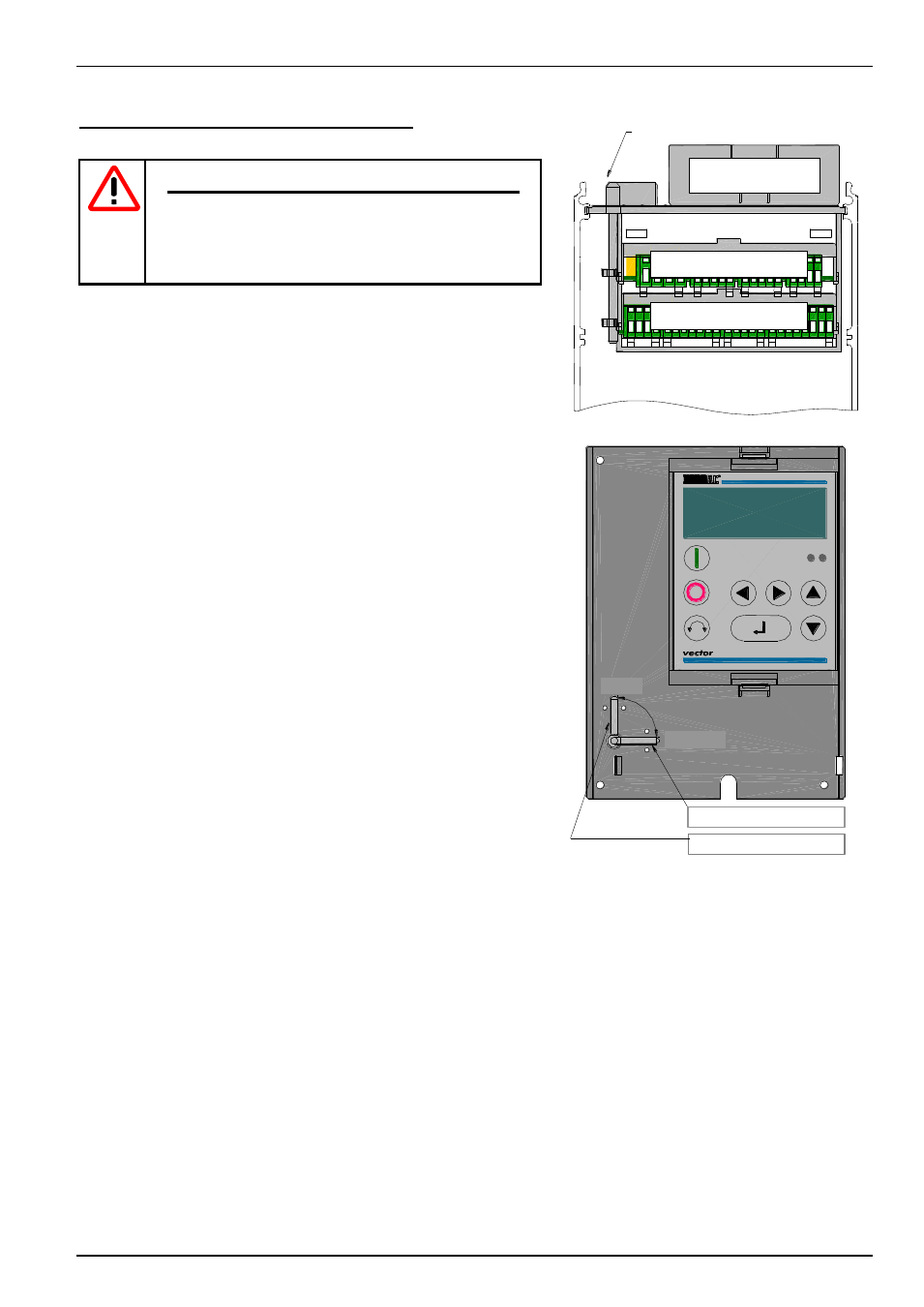
Installation of the special extension units
NOTE
Installation must be carried out by qualified personnel
only, paying particular attention to safety and warning
instructions.
Customer units must not be inserted/removed when
live.
1. Switch off the mains voltage, observe the waiting period.
2. Remove the cover grid from the connection area by loosening the 2
screws and levering out the device cover (slot) or simply pull it out.
3. Locking lever in the "open" position.
4. Using light pressure push the special extension unit into the lower
guide rail until it engages.
5. Move the locking lever to the "closed" position.
6. Remove the connector by pressing the releases then make the
necessary connections. Then insert the connectors until they engage.
7. Replace all covers.
Customer unit
Locking pin
CLOSED
OPEN
Locking device closed
Locking device open
Technology unit
Special extension unit