Menu structure – NORD Drivesystems BU0700 User Manual
Page 25
3.1 Technology unit
BU 0700 GB-1411
Subject to technical alterations
25
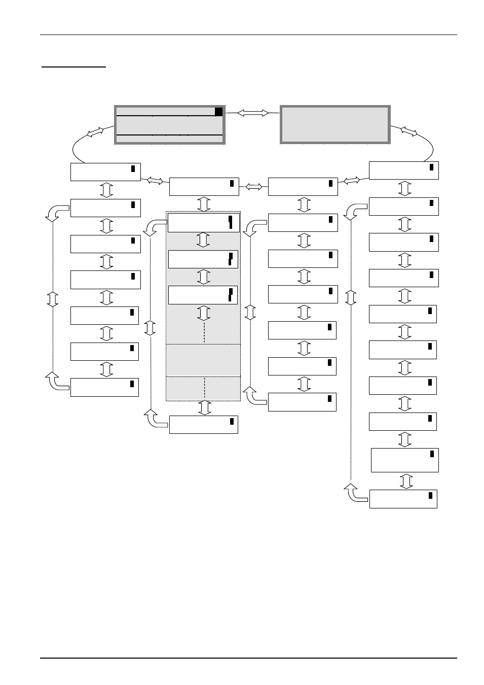
Menu structure
The menu structure consists of various levels that are each arranged in a ring structure. The ENTER key moves the menu on to
the next level. Simultaneous operation of the SELECTION keys moves the menu back a level.
Parameter
1
management
P1201
2
Copy - Source
P1202
2
Copy - Target
P1204
2
Load default values
P1203
2
Copy - Start
P1205
2
Delete memory
P0
2
Back
Parameterization
1
Display
1
P1001
2
Bus scan
P1002
2
FI selection
P1004
2
Values for display
P1003
2
Display mode
P1005
2
Standardisation
factor
P0
2
Back
Options
1
P1301
2
Language
P1302
2
Operating mode
P1304
2
Contrast
P1303
2
Automatic bus scan
P1305
2
Set password
P1306
2
Box password
P0
zurück
700E 3,0kW/3 POS STD
1
Fi/Hz
U/V
I/O
45.0
360
3.4
ONLINE
FI P1
R RUNNING
U1
U2
U3
U4
U5
1
-
-
-
-
OK
-
-
-
-
100
P1307
2
Reset box paramet.
P0
2
Back
P0
zurück
P1308
2
NORDAC p-box
Version 3.9
Basic parameters
2
>ENTER<
(to level
3
)
P0
2
Back
Inverter menu structure,
dependent on installed
options (e.g. posicion, etc.)
Section 5
Parameterisation
Motor data
2
>ENTER<
(to level
3
)
Operating displays
2
>ENTER<
(to level
3
.)
>Display< (P10xx), >Parameter management< (P12xx) and >Options< (P13xx) are purely ParameterBox parameters and have
nothing directly to do with the inverter parameters.
Access to the inverter menu structure is gained via the >Parameterisation< menu. The details depend upon the customer units
(SK CU1-...) and/or special extension units (SK XU1-...) connected to the inverter. The description of parameterisation begins in
Chapter 5.