2 customer units – NORD Drivesystems BU0700 User Manual
Page 41
3.2 Customer unit
BU 0700 GB-1411
Subject to technical alterations
41
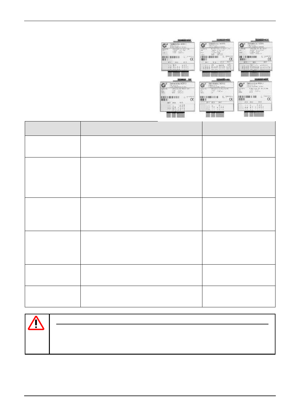
3.2 Customer units
(Customer Units, Option)
Customer units are optional push-in modules whose slots are
located inside the frequency inverter. Following insertion and
switching on the mains supply, they are automatically identified
by the inverter, and the required parameters are made available.
Cable connection is via direct plug-in clip connectors with spring
terminals. This makes the connection of devices very easy and
convenient.
Customer unit
SK CU1-...
Description
Data
Basic I/O
SK CU1-BSC
Simplest custom interface for optimum adaptation to the
application.
1 x multifunction relays
3 x digital inputs
1 x analog input, 0...10V
Standard I/O
SK CU1-STD
Upgraded functionality of control signals, including USS
bus control.
2 x multifunction relays
4 x digital inputs
1 x analog input, 0...10V,
0/4...20mA
1 x analog outputs, 0...10V
1 x RS 485
Multi I/O
SK CU1-MLT
Top functionality of digital and analog signal processing.
2 x multifunction relays
6 x digital inputs
2 x analog inputs, -10...+10V,
0/4...20mA
2 x analog outputs, 0...10V
Multi I/O
SK CU1-MLT-20mA
Top functionality of digital and analog signal processing.
2 x multifunction relays
6 x digital inputs
2 x analog inputs, -10...+10V,
0/4...20mA
2 x analog outputs, 0/4...20mA
Profibus
SK CU1-PBR
This interface enables control of the NORDAC SK 700E
via the Profibus DP serial port.
1 x multifunction relays
1 x digital inputs
1 x Profibus
CAN bus
SK CU1-CAN-RJ
This unit enables control of the NORDAC SK 700E via
the CANbus port.
1 x multifunction relays
5 x digital inputs
2 x CANbus connectors RJ45
NOTE
,
for 5V / 15V power supplies
The customer units and special extension units currently have various power supplies (5V / 15V) that can
be used externally. The maximum permissible external load current is 300mA. This can be taken from
one or more power supplies. The total current must however not exceed 300mA.
All control voltages are based on a common reference potential!
Potentials AGND /0V und GND /0V are internally linked in the device.