NORD Drivesystems BU0700 User Manual
Page 18
NORDAC SK 700E Operating Manual
18
Subject to technical alterations
BU 0700 GB-1411
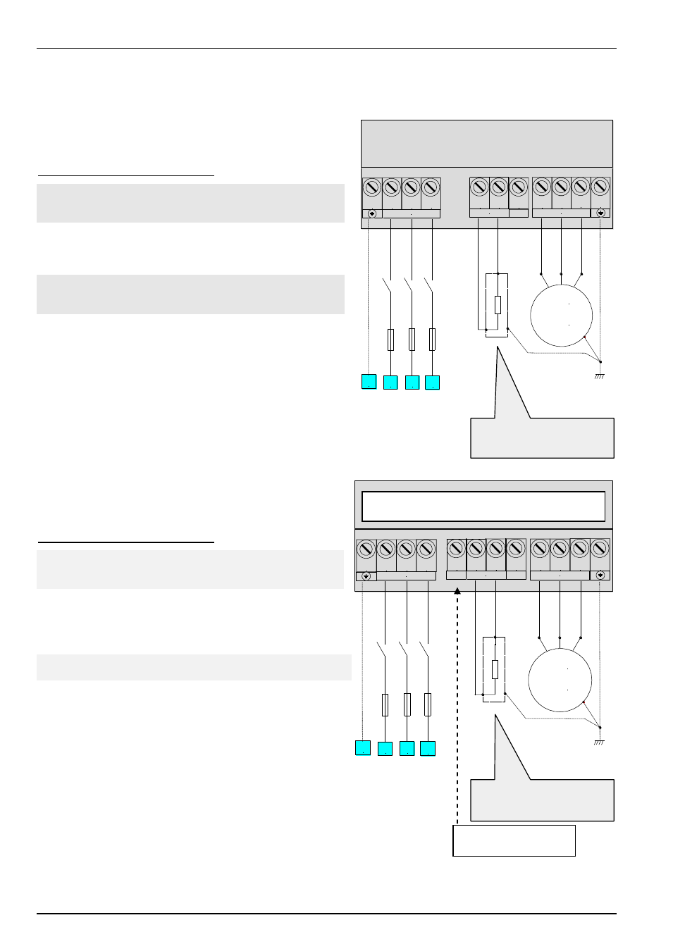
-ZW BR +ZW PE
PE L1 L2 L3
M
3 ~
L3
L2
L1
PE
Input
PE
W
U V
Output
BR
2.10.2 Mains connection up to 22kW (PE/L1/L2/L3)
No special safety devices are required on the mains input side for
the frequency inverter, just the normal mains protection (see
technical data) and a master switch/fuse.
Connection terminals cross-section:
SK 700E-151-340-A ...
SK 700E-751-340-A
VDE
4mm²
(0.5 … 0.6Nm)
UL/cUL
(AWG 24-10)
SK 700E-112-340-A ...
SK 700E-152-340-A
VDE
10mm²
(1.2 … 1.5Nm)
UL/cUL
(AWG 22-8)
SK 700E-182-340-A ...
SK 700E-222-340-A
VDE
25mm²
(2.4 … 4.0Nm)
UL/cUL
(AWG 16-4)
Note:
The use of this inverter on an IT network is possible
after minor alterations. Please consult your supplier.
2.10.3 Mains connection from 30kW (PE/L1/L2/L3)
No special safety devices are required on the mains input side for
the frequency inverter, just the normal mains protection (see
technical data) and a master switch/fuse.
Connection terminals cross-section:
SK 700E-302-340-O ...
SK 700E-372-340-O
VDE
35mm²
(6 … 8Nm)
(PE terminals = 16mm
2
)
UL/cUL
(AWG 2)
SK 700E-452-340-O ...
SK 700E-552-340-O
VDE
25-50mm²
(6 … 8Nm)
UL/cUL
(AWG 4-0)
SK 700E-752-340-O
…
VDE
95mm²
(15 … 20Nm)
SK 700E-902-340-O
UL/cUL
(AWG 000)
SK 700E-113-340-O ...
SK 700E-163-340-O
VDE 50-150mm²
(25 … 30Nm)
(PE terminals = 35-95mm
2
) UL/cUL
(AWG 0-300 MCM)
Note:
The use of this inverter on an IT network is possible
after minor alterations. Please consult your supplier.
Note:
Only one PE terminal is located near the mains connection in the 90kW
device. Further PE connections can be implemented on the device housing.
PE L1 L2 L3
M
3 ~
L3
L2
L1
PE
Input
+B -B
Brake
-DC
PE
W
U V
Output
Brake resistor
Optional, Chap. 2.7/2.8
Brake resistor
Optional, Chap. 2.7/2.8
Some of the PE connections are in the support
plate, near to the terminal bar
Do not use ZW, the
connection is sealed.