2 assembly and installation, 1 installation – NORD Drivesystems BU0700 User Manual
Page 8
NORDAC SK 700E Operating Manual
8
Subject to technical alterations
BU 0700 GB-1411
2 Assembly and installation
2.1 Installation
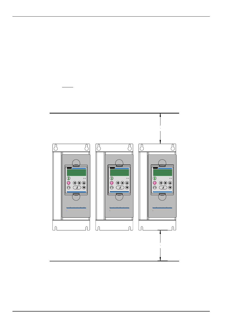
NORDAC SK 700E frequency inverters are available in various sizes depending on the output. When installed in a control
cabinet, the size, power dissipation and perm. ambient temperature must be taken into account to prevent device failures.
The equipment requires sufficient ventilation to protect against overheating. Reference values apply here for the spaces above
and below the frequency inverter within the control cabinet.
(up to and inc. 22kW, above > 100mm, below > 100mm and from and inc. 30kW above > 200mm, below > 200mm)
Electrical components (e.g. cable ducts, contactors, etc.) can be located within these limits. There is a height-dependent
minimum separation distance from the frequency inverter for these components. This distance must be a minimum 2/3 of the
object height. (Example: cable duct 60mm high 2/3
60mm = 40mm gap)
Additional side gaps for devices up to and inc. 55kW are not required. Mounting can be immediately next to each other. The
installation position is normally vertical. It must be ensured that the cooling ribs on the rear of the device are covered with a flat
surface to provide good convection.
Warm air must be vented above the device!
If several inverters are arranged above each other, ensure that the upper air entry temperature limit is not exceeded. (See also
Chapter 7, Technical data). If this is the case, it is recommended that an "obstacle" (e.g. a cable duct) is mounted between the
inverters so that the direct air flow (rising warm air) is impeded.
700E
N O R D A C
R
700E
N O R D A C
vector
R
700E
N O R D A C
R
700E
N O R D A C
vector
R
700E
N O R D A C
R
700E
N O R D A C
vector
R
>100/200 mm
>100/200 mm